Daktronics Digit Display Installation with FLR-500 Control Kit User Manual
Signal installation
Quick Guide: Digit Display Installation with FLR-500 Control Kit
p. 1
DD1399078-Rev0
PO Box 5128, 201 Daktronics Drive, Brookings, SD 57006
27 August 2008
Tel: 866-343-3122 Fax: 605-697-4444
Note: This guide begins after the displays have been physically mounted.
Signal Installation
1. Choose a location for the receiver on the side of a display that faces the
building. The location should be high off the ground with an
unobstructed line-of-sight to the store.
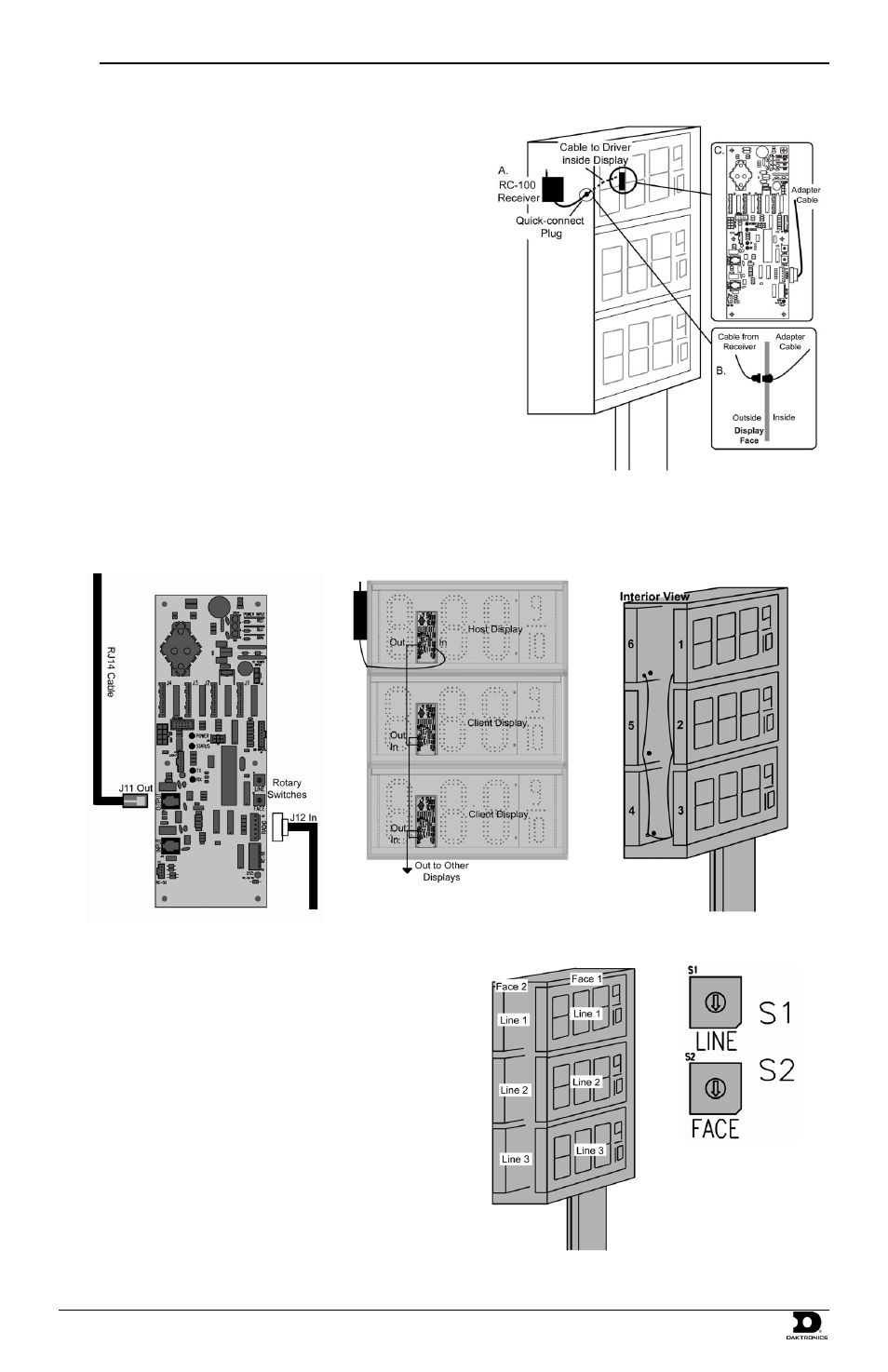
2. Mount the radio receiver to the chosen location using screws (Figure 1,
A). Take care not to damage the display to help prevent water from
entering the display and damaging the internal components.
3. Mount the adapter cable quick-connect jack to the display cabinet so that
the receiver quick-connect can be attached from the outside (Figure 1, B).
A 5/8” hole will be required.
4. Grease each signal jack with electrical contact grease before making the
following signal connections.
5. Connect the quick-connect from the receiver to the adapter cable.
6. Plug the other end of the adapter cable into the driver board 6-pin jack
(J12), as shown in Figure 1, C.
7. Remove the signal knockouts on the backs of each display. Insert
conduit fittings over the rough edges.
8. Starting with the driver board plugged into the receiver (the host
display), plug the RJ14 cable into the output jack (J11).
9. Plug the other end of this cable into the Input jack (J13) on the next display driver. Continue with this pattern, going from the output of one
driver to the input of the driver in the next display. Refer to Figure 3 and Figure 4 for signal routing overviews.
Note: Three displays are shown per face, but the transmitter can control up to five displays per face.
10. After plugging in the RJ cable(s) on a driver, set the display line and
face numbers using the rotary switches on the driver (Figure 6).
11. Each installation consists of faces with multiple displays installed in
each face. The displays are referred to as “lines” on the rotary switch
(Figure 6). A different line and face number must be set for each
display driver. Use Figure 5 as a guide for setting the driver line and
face numbers.
Figure 1: Radio Installation
Figure 2: Driver Connections
Figure 3: Signal Routing by Display
Figure 4: Signal Routing
Figure 5: Line and Face Number
Pattern
Figure 6: Rotary
Switches on Driver