Codan Radio Radio Repeater Systems Training Guide User Manual
Page 22
TRAINING GUIDE | RADIO REPEATER SYSTEM
Chapter 2: Repeater System Confi gurations
Page 14
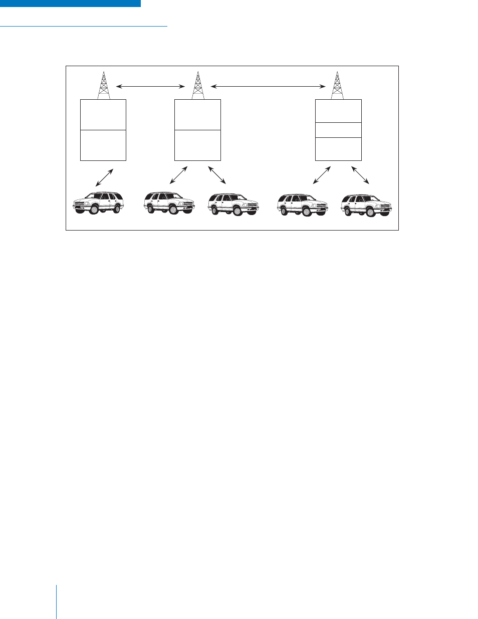
Figure 2-7: Partial DTMF Controlled Link System
With the arrangement shown in Figure 2-7, mobiles (A), (B) and (C) are in constant communication.
Mobiles (D) and (E) can be communicating between themselves at the same time without interference
from the others. All mobiles will be in contact with each other by activating the DTMF switch.
Mobile (A)
Mobile (B&C)
Mobile (D&E)
Link
Repeater
Drop
Repeater
Link
Repeater
DTMF
Drop
Repeater
Link
Repeater
Drop
Repeater