42 user guide, Pin 1, Wire sizes: 22 awg min, 16 awg max – Codan Radio MT-4R User Manual
Page 50: Pin 16
UG-001 Daniels MT-4R and MT-4D Radio Systems
www.danelec.com
Chapter 6: Radio System Components
42
User
Guide
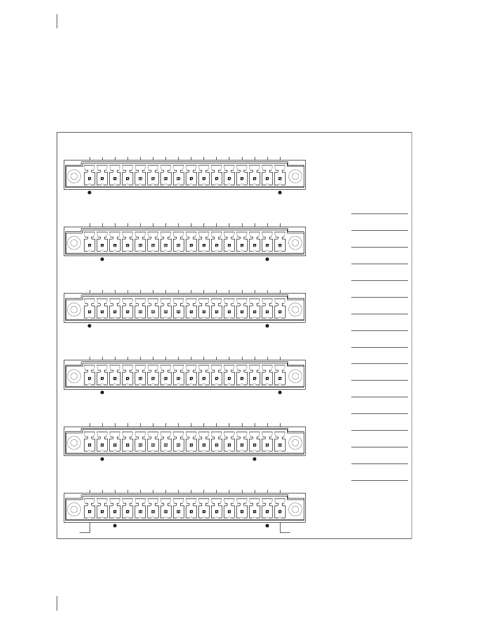
A close-up view of the auxiliary connector label, as shown in Figure 6-5, indicates the short signal name
for each connection point. Defi nitions for these signals can be found in the SR-39-1 subrack manual.
Extra connectors (Spare, Alarm, IMC) that can be used for different functions depending on the control
card are listed to the right of the connectors. For example, the CI-BC-4E base controller uses these
lines for auxiliary audio inputs / outputs and auxiliary COR / PTT connections. The custom functions of
these connectors will be marked in the blank space next to the signal name.
Figure 6-5: Auxiliary Panel Pin-Out
J1
Tx A
CSel D2
J2
Tx A
CSel D0
Tx A
CSel D1
Tx A
CSel D3
Rx
A CSel D0
Rx A
CSel D1
Rx A
CSel D2
Rx A
CSel D3
Tx B CSel D0
Tx B CSel D1
Tx B CSel D2
Tx B CSel D3
Rx B CSel D0
Rx B CSel D1
Rx B CSel D2
Rx B CSel D3
J3
Spare 1
Spare 2
Spare 3
Spare 4
Spare 5
Spare 6
IMC 1IMC 2Alarm 1
Alarm 2
Alarm 3
Alarm 4
Alarm 5
Alarm 6
Alarm 7
Alarm 8
Ground
Ground
Ground
Ground
13.8 Vdc
13.8 Vdc
9.5 Vdc
9.5 Vdc
Rx
A Sql Over
Rx
A Prior COR
Rx A
Disc LP
O/P
Rx A
Sql De-emp
Rx B Sql Over
Rx B Prior COR
Rx B Disc LP
O/P
Rx B Sql De-emp
J4
Tx A
Audio
Cntl
Tx A
VSWR Fwd
Tx A
VSWR Rev
Tx A
Dir Mod
Tx A
Subt I/P
2
Tx A
PTT
Out
Rx A
Sig Stren
Rx A
Mute
Tx B
Audio Cntl
Tx B VSWR Fwd
Tx B Dir Mod
Tx B Subt I/P
2
Tx B PTT
Out
Rx B Sig Stren
J5
Tx B VSWR Rev
Rx B Mute
Tx A
Standby
Rx A
Amp Aud
Rx
A Sql Flat
Rx A
9.5V
Rx A
9.5V Mon
Rx A
Iso COR
A
Rx A
Iso COR K
Tx B Standby
Rx B
Amp Aud
Rx B Sql Flat
Rx B 9.5V
Rx B 9.5V Mon
Rx B Iso COR
A
Rx B Iso COR K
5W Rx
Audio
IMC 3
J6
Pin 1
Pin 16
Wire Sizes: 22 AWG Min, 16 AWG Max
Spare 1
Spare 2
Spare 3
Spare 4
Spare 5
Spare 6
IMC 1
IMC 2
Alarm 1
Alarm 2
Alarm 3
Alarm 4
Alarm 5
Alarm 6
Alarm 7
Alarm 8
IMC 3
Tx A
Bal I/P
1
Tx A
PTT
Rx A
Bal O/P
1
Rx A
Bal O/P
2
Rx A
COR
Rx A
Disc O/P
Tx B Bal I/P
1
Tx B Bal I/P
2
Tx B PTT
Tx B Subt I/P
1
Rx B Bal O/P
1
Rx B Bal O/P
2
Rx B COR
Rx B Disc O/P
Tx
A Subt I/P
1
Tx A
Bal I/P
2