Installation in kitchen cabinet with door, Choosing suitable sur- roundings, Discharging products of combustion – Caple C762GSS User Manual
Page 12
28
INSTALLATION IN KITCHEN
CABINET WITH DOOR
(fig. 4.5)
It is recommended that a 30 mm clear-
ance be left between the cooker top and
the fixture surface (fig. 4.5).
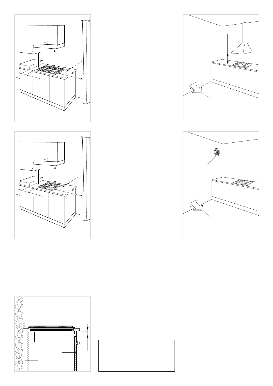
30 mm
Fig. 4.5
Space for
connections
Clearance
Door
CHOOSING SUITABLE SUR-
ROUNDINGS
The room where the gas appliance is to
be installed must have a natural flow of
air so that the gas can burn (in
compliance with the current laws in
force).
The flow of air must come directly from
one or more openings made in the
outside walls with a free area of at least
100 cm
2
.
If the appliance does not have a no-
flame safety device this opening must
have an area of at least 200 cm
2
.
The openings should be near the floor
and preferably on the side opposite the
exhaust for combustion products and
must be so made that they cannot be
blocked from either the outside or the
outside.
When these openings cannot be made,
the necessary air can come from an
adjacent room which is ventilated as
required, as long as it is not a bedroom
or a danger area (in compliance with the
current laws in force).
In this case, the kitchen door must allow
the passage of the air.
DISCHARGING PRODUCTS
OF COMBUSTION
Extractor hoods connected directly to the
outside must be provided, to allow the
products of combustion of the gas appli-
ance to be discharged (fig. 4.6).
If this is not possible, an electric fan may
be used, attached to the external wall or
the window; the fan should have a capac-
ity to circulate air at an hourly rate of 3-5
times the total volume of the kitchen (fig.
4.7).
The fan can only be installed if the room
has suitable vents to allow air to enter, as
described under the heading “Choosing
suitable surroundings”.
Intensive and prolonged use may
require extra ventilation, e.g. opening
a window, or more efficient ventilation
increasing the mechanical suction
power if this is fitted.
Fig. 4.3
Fig. 4.4
650 mm
60 mm min
200 mm min
500 mm
450 mm
650 mm
60 mm min
200 mm min
500 mm
450 mm
H min 650
mm
Fig. 4.6
Air vent
Extractor hood
for products of
combustion
Fig. 4.7
Air vent
Electric fan to
extract products
of combustion