Burst Electronics BG-3 User Manual
Page 3
USB-B connector
Facilitates connection to your Windows XP based PC for installing a station identifying OSD
image (24-Bit BMP).
OSD LED (On-Screen Display)
When ON, your station ID is being overlaid upon the “Test Pattern” BNC output. During upload
of the BMP image, the LED flashes rapidly.
10-Position Rotary
Allows selection of the test pattern that is routed on the “Test Pattern” BNC output. Rotate this
switch to select each pattern. On the BG-7, the black burst outputs will not have the OSD
image displayed. Selectable patterns;
Red Green
Blue Window
5-Step Luma 5-Step Chroma
10-Step Chroma PGM OSD (Black Burst)
SMPTE Bars 75% Full Field Bars
OSD On/Off
Allows the OSD image to be turned on or off.
Power LED
Indicates if the unit is powered.
Power Switch
Allows you to turn the unit on or off.
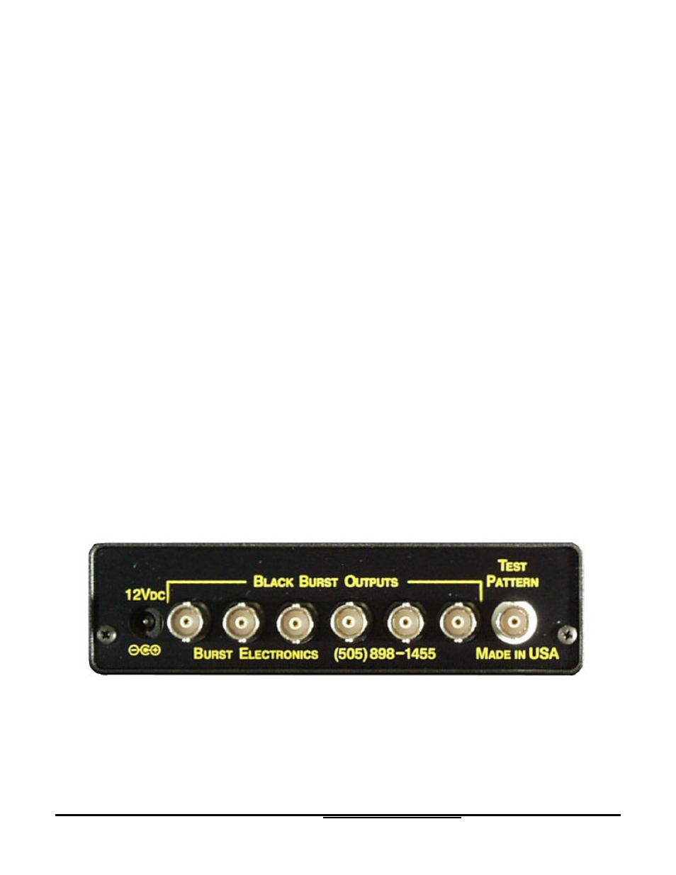
Rear Panel
The BG-3 rear panel has two (2) connectors, one (1) 12Vdc power connector and one (1) Test
Pattern BNC connector. The BG-7 rear panel (shown above) has eight (8) connectors, one (1)
12Vdc power connector, six (6) Black Burst BNC connectors, and one (1) Test Pattern BNC
connector.
BG-3 and BG-7 Test Pattern Generator
3