Broadata Communications LBC-HDMI-R-SCL User Manual
Page 6
LBC-HDMI-R-SCL User’s Manual
Link Bridge
TM
HDMI Scaler System
Broadata Technical Support, [email protected]
7
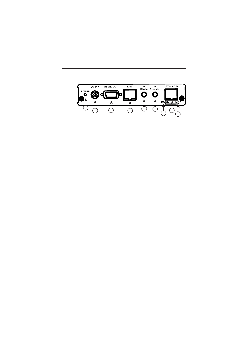
2.2 Rear Panel
1. Power LED:
This LED will illuminate when the device is connected to a power
supply.
2. DC 24V:
Plug the 24 V DC power supply into the unit and connect the
adaptor to an AC outlet. Only one side of power is needed to
activate both Transmitter and Receiver when both obtain the
PoH function.
3. RS-232 OUT:
This slot is to connect with D-Sub 9-pin cable from device
equipment for receiving RS-232 commands. Commands are
listed in Appendix B.
4. LAN:
Connect to an active network for LAN sharing of a total
transmission rate up to 100Mbps. Or when a compatible LAN
equipped Transmitter is connected to an active network, this
allows the network access (including internet access if available)
to be shared between the Transmitter and Receiver. Connect
any Ethernet equipped device e.g. a Smart TV or games console
to the LAN port for that device to share the network internet
access.
Note: DO NOT connect LAN cable with any of the
CAT5e/6/7 port. Doing so may trigger power shut down
and ruin the device
5. IR Blaster:
Connect to the supplied IR Blaster cable for IR signal
transmission. Place the IR Blaster in direct line-of-sight of the
equipment to be controlled.
1
2
3
4
5
6
7
9
8