Specifications, Terminals and connections, Low voltage – Boyertown nrgMax Universal Oil Control V4.0 User Manual
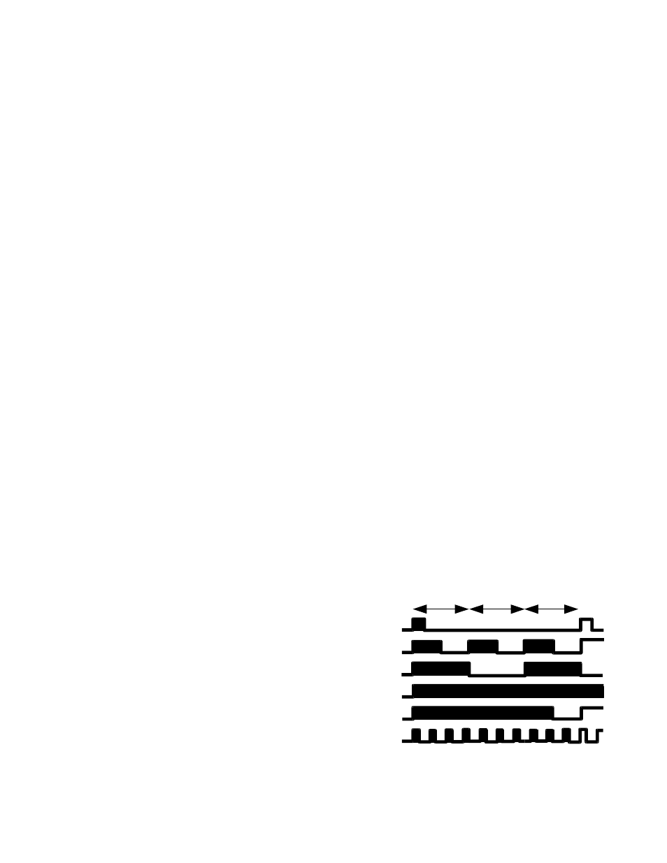
Page 4: Line voltage, Burner connections, Status led flashing patterns, 1sec 1 sec 1 sec
SPECIFICATIONS
•
Electrical Ratings:
◦
Power Requirements:
▪
Voltage: 24Vac, 50/60 Hz.
▪
Current: 4 VA at 24 Vac.
▪
PTC Fuse (resettable) trips at 4.5A
◦
Contact Ratings:
▪
Circulating Fan: 15A Full Load, 30A Locked
Rotor at 115 Vac (includes optional EAC
load).
▪
Burner: 5.8 A Continuous Load (7.4A with
interrupted ignition)
•
Settings: Standard Configuration
◦
Heating:
▪
Blower On Delay: 30 or 75 seconds, field-
adjustable
▪
Blower Off Delay (BOD): 90, 120, 150, 180
seconds, field-adjustable.
◦
Timing Tolerance: less than 1 second
•
Environmental Ratings:
◦
Temperature: -40 to +150° F [-40° to +66° C].
◦
Humidity: 95% maximum, non-condensing.
Terminals and Connections:
Low Voltage:
•
Thermostat:
◦
G:
Blower On
◦
W:
Call for heat (0.08A load)
◦
R:
24VAC out to thermostat
◦
Y1:
Cooling, Stage 1
◦
C:
24Vac common
◦
W2:
Heating, Stage1
◦
Y2:
Cooling, Stage2
◦
Yx:
Dummy terminal, no connection
◦
O:
Heat pump reversing valve
◦
DH:
Dehumidification
•
CLASS 2 TRANSFORMER 50VA Max (overload
protected)
◦
X:
24VAC
◦
C
24VAC Common
•
16-PIN ECM Connector: Convenient interface
between 10-position thermostat, DIP-switches and
ECM motors.
•
•
Option Jumpers: Selectable Options:
◦
F1 Reserved
◦
F2 Enhanced PSC Mode
◦
F3 Extended Blower On Delay (75 Sec)
Line Voltage:
•
Unused: No connection (2 terminals)
•
L1:
120VAC 60Hz, 1ph, 15 A mp (Max) supply
•
N:
120VAC Neutral supply
•
Neutrals: Connection points for loads, tied internally
to N (6 terminals)
•
120VAC : L1 supply to accessories, continuously
powered (3 terminals)
•
Cont.
120VAC to Continuous speed of blower.
Normally energized, it is de-energized whenever
Cool or Heat terminals are energized
•
EAC:
120VAC to Electronic Air Cleaner.
Energized along with Cool or Heat terminals
•
Heat:
120VAC 15A, 1HP blower speed.
•
Cool:
120VAC 15A, 1HP blower speed
•
H:
120VAC 1A to Humidifier. Powered by
burner motor feedback (Pins 7-8 on 9-pin burner
connector).
Burner Connections:
•
9-PIN AMP Connector:
(MATES WITH TYCO PART #350720)
1)
Safety Limit string (return)
2)
120VAC to Oil Burner (high-limit protected)
3)
Burner T-T (internally connected to Pin 6)
4)
Neutral (internally connected to Pin5 and N)
5)
Neutral (internally connected to Pin 4 and N)
6)
Burner T-T (internally connected to Pin 3)
7)
Burner Motor (internally connected to Pin 8)
8)
Burner Motor (internally connected to Pin 7)
9)
120VAC to Safety Limit string. Normally off,
energized on call for heat by Relay K1
•
Edge Connector (Alternate, 6 conductor) mates with
Molex 09-01-6061.
◦
Motor: Burner Motor
◦
Limit: 120VAC to Safety Limit string. Normally
off, energized on call for heat by Relay K1
◦
Limit: Safety Limit string (return)
◦
L1: 120VAC to Oil Burner (high-limit
protected)
◦
120V: 120VAC Continuous (not limit protected)
Status LED Flashing Patterns
nrgMAX
(division of Bob Tonner Applied Research Inc)
Pickering, ON, 289-800-7131 www.nrgmax.ca
1
sec
1
sec
1
sec
Standby
Heating
Cooling
Limit
Limit reset
No Burner