Ecm motor operating modes – Boyertown Regal Oil Fired Furnace Variable Speed 2 Stage ECM Motor User Manual
Page 9
MULTIPLE FURNACES IN COMMON DUCT WORK
Multiple furnaces connected to common duct work, either supply, return, or both supply
and return must be wired so that all furnace blower motors are energized at the same time.
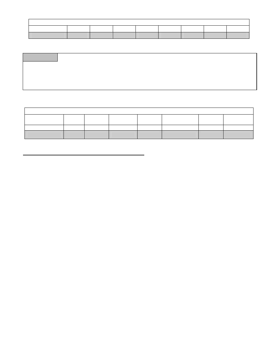
Table 5 Round Duct Equivalent Area
Nominal
Size
4 5 6 7 8 9 10 12
Area in.
2
12.5
19.6
28.3
38.5
50.3
63.6
78.5
113.1
WARNING
Failure to turn all blowers on at the same time can cause a reversal of air flow in those units where the
blower motor is not operating. This reversal of air flow can cause premature blower, blower motor,
wiring and or heat exchanger failure.
Please consult the factory for specific wiring instructions for your application.
Table 6 Blower Specifications
Model HP
Speeds
RPM
Volts
Full
Load Amp.
Rotation Blower
Model
LB/HB 750
3/4
Variable
1400 Max
115
9.6
CCW
100-10T
LB/HB 1000
3/4
Variable
1400 Max
115
9.6
CCW
100-10T
ECM MOTOR OPERATING MODES
Introduction
The ECM 2.3 motor is a variable speed, high effiency motor which has the ability to produce constant
air flow within a system, independent of static pressure. It achieves constant air flow by adjusting
speed and torque to account for changes in system static pressure. The GE ECM uses a proprietary
mathmatical algorithm to model air moving systems driven by forward curved blower wheels.
Operating Modes
The ECM motor is controlled by 24VAC thermostat signals to determine which mode of operation the
blower is to run. Air flow rates in the different modes are controled by the setting of the DIP
switches.
Standby Mode:
The thermostat inputs are being continuously monitored . The motor will respond to the 24
volt AC input signal from the thermostat.
Fan Mode:
When a call for fan operation is received from the thermostat (“G” line is energized) the
blower will operate at a reduced speed as determined by the position of the cooling DIP
switches as set for the airconditioning speed. See air flow tables for DIP switch and air flows.
If a call for cooling or for heating is energized along with the call for fan only the unit will run
at the respective air flow for heating or cooling.
Cooling Mode:
When a call for cooliong is received from the thermostat (“Y” line is energized) the motor will
operate at the cooling speed and profile as adjusted by the cooling DIP switches. Cooling air
flow is profiled to ramp the air flow up to the full cooling air flow to allow for maximum
dehumidification
Heat Mode:
When a call for heat is received from the thermostat (“W” line is energized) the motor will
9