Electrical data, Pin assignment of the connectors – BECKHOFF C6640 User Manual
Page 18
Installation Instructions
signal lamp connection or via a contactor. With this solution the main
switch generally only has to be switched off if the control cabinet has to be
opened. The battery will only be used in the event of a power failure.
In order to maintain a screen display for the Industrial PC in the event of a
power failure, the power supply unit is equipped with a UPS output 27 V /
1.4 A for connecting a Control Panel with a display dimension up to 19
inches. This enables a power failure to be visualized and displayed to the
user. Once the PC has shut down, the UPS output is switched off.
For a detailed functional description please refer to section
Electrical Data
Input voltage:
22 – 30 V DC
Current consumption:
10 A (22 V)
Output capacity:
150 W (max.)
Current carrying capacity of
the 24 V power supply unit
Output voltages from the
24 V power supply unit
Current loading
maximum
+ 5 V
14 A
- 5 V
0.3 A
+ 12 V
12 A
- 12 V
0.5 A
+ 3,3 V
12 A
5 V VSB
1.5 A
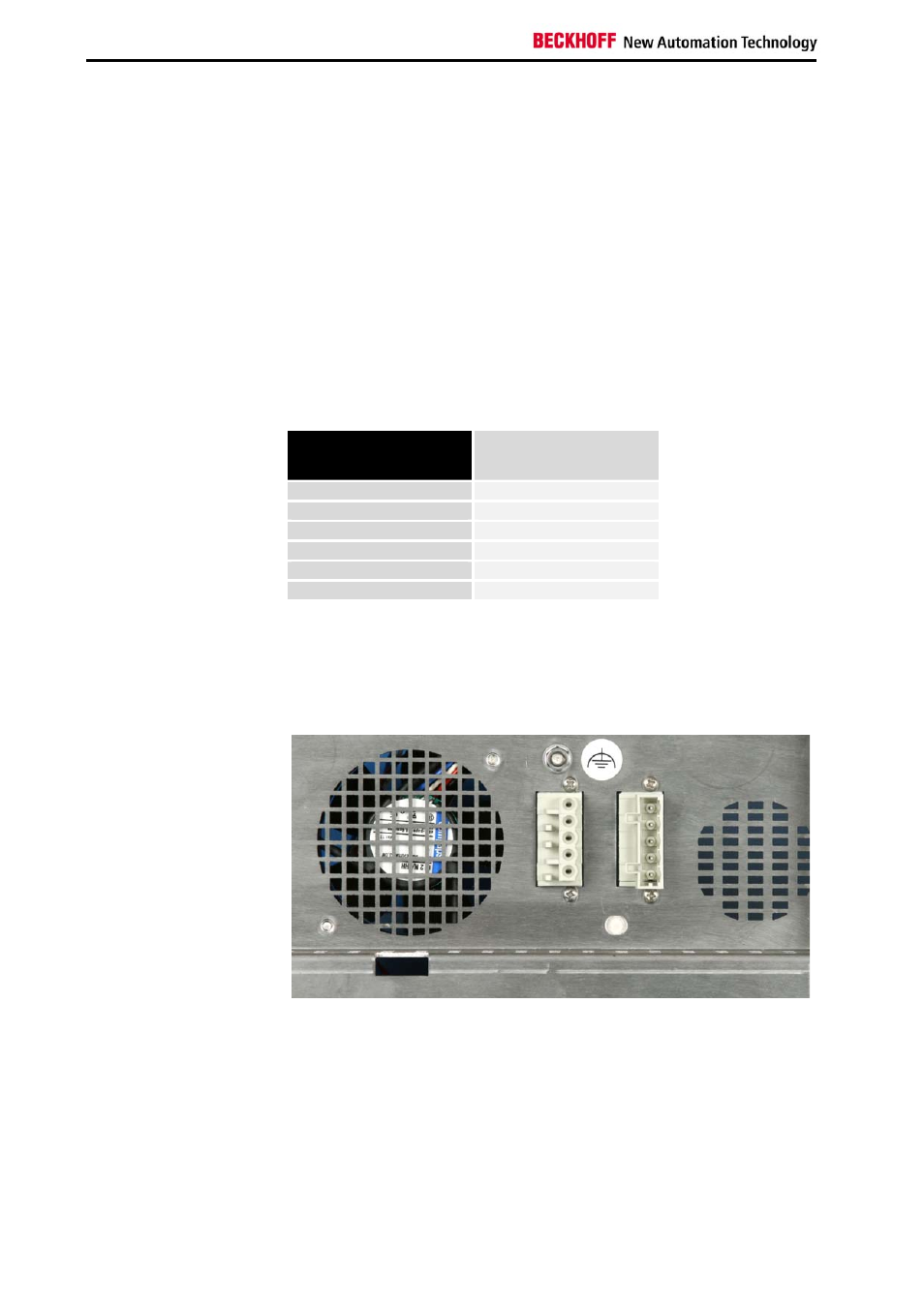
Pin assignment of the connectors
Two 5-pin plug connectors with CAGE CLAMP connection (see photo) are
installed at the PC housing in order to connect the 24 V
DC
power supply
and the external components.
Plug connectors with CAGE
CLAMP connection
X101
X102
16
C6640, C6650