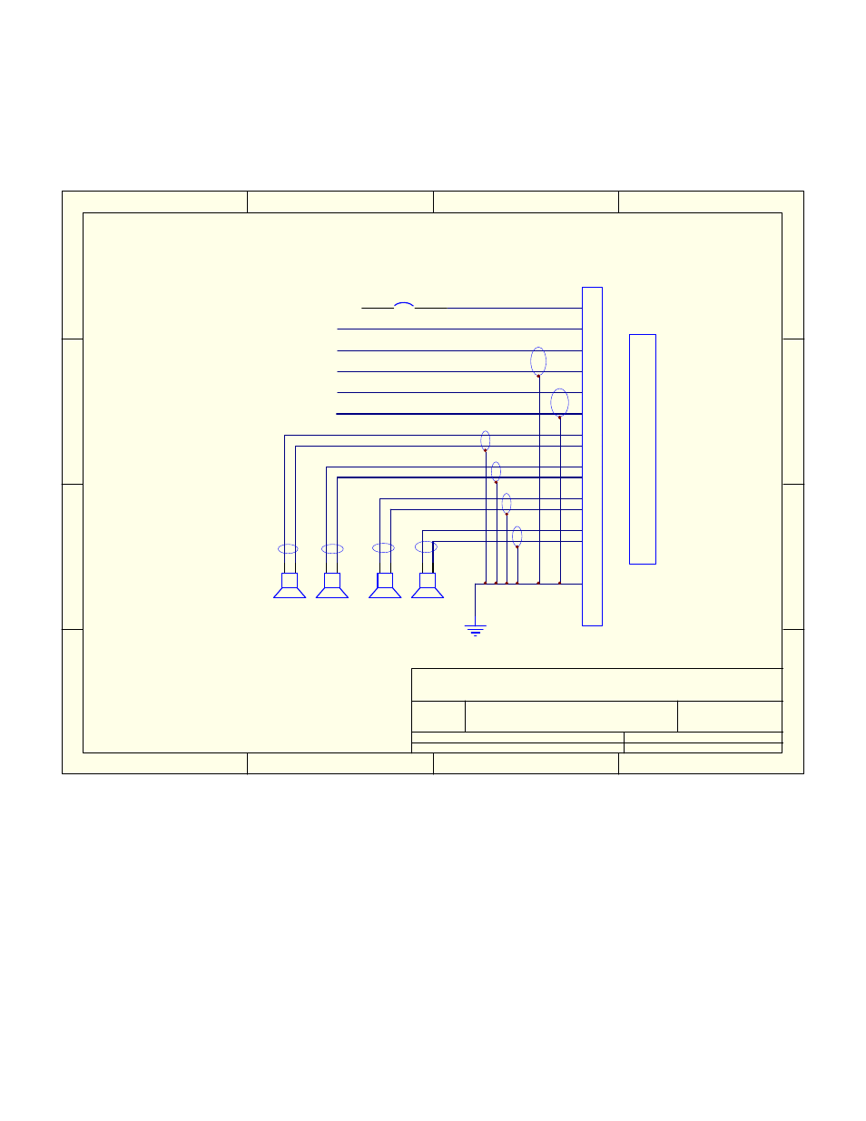
Ai-amplifier installation schematic – Avionics Innovations Speaker Amp User Manual
Page 4
1
2
3
4
A
B
C
D
4
3
2
1
D
C
B
A
Title
Number
Revision
Size
Letter
Date:
12-Oct-1999
Sheet of
File:
C:\ADVSCH\DRW\17901.SCH
Drawn By:
8
15
14
7
13
6
1
10
2
9
11
4
12
5
3
RF
LF
RR
LR
5 Amp To Avionics Buss
AI-Amplifier Installation Schematic
17901-00
NC
1
1
R.A.P.
AI-Amplifier 17001-14v or 17001-28v
+
-
+
-
+
-
+
-
5
Remote on
Right Rear Input
Left Rear Input
Right Front Input
Left Front Input
This installation schematic is universal
for both the 14 and 28 volt versions
Please ensure you have the right unit
for your application. Warranty will be void
if the wrong voltage is applied
The" Remote on" should be connected to the remote on output
of the head device. This prevents the amplifier from operating
withoout the head unit being on. If this option is not available
on the head unit, use a 1 amp switch and in line 1 amp fuse
and hook to the avionics buss.