Venting installation instructions – Desa (V)TC36N SERIES User Manual
Page 14
www.desatech.com
116192-01B
14
VENTING INSTALLATION
INSTRUCTIONS
Continued
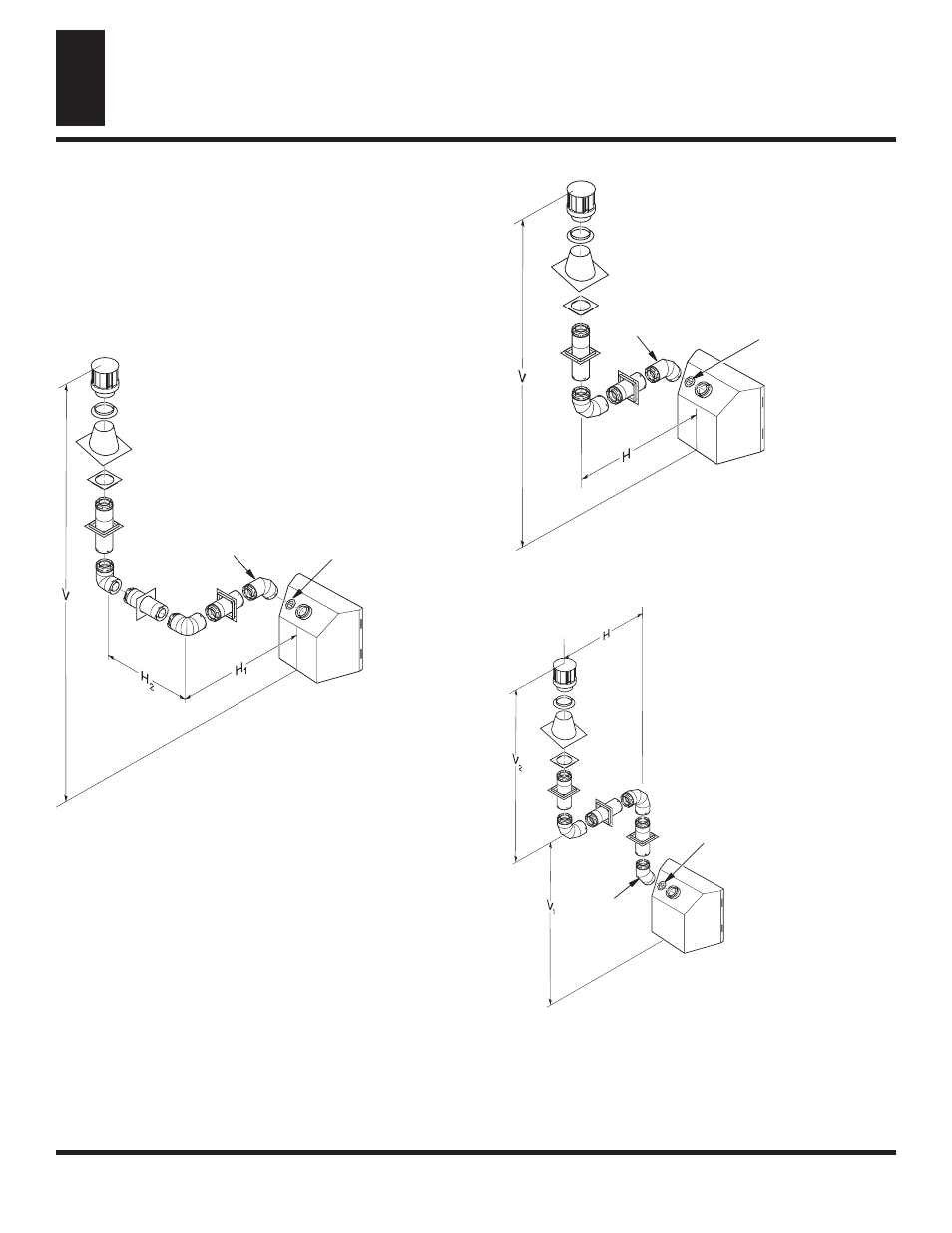
Vertical Termination Configurations
Figures 21 through 24 show four different configurations for verti-
cal termination.
Venting with Two 90° Elbows
Vertical (V)
Horizontal (H
1
) +
Horizontal (H
2
)
5' min.
2' max.
6' min.
4' max.
7' min.
6' max.
8' min.
8' max.
20' max.
8' max.
Figure 21 - Vertical Venting Configuration Using Two 90°
Elbows with Two Horizontal Runs (Vertical Round High Wind
Termination Shown)
Venting with One 90° Elbow
Vertical (V)
Horizontal (H)
5' min.
2' max.
6' min.
4' max.
7' min.
6' max.
8' min.
8' max.
20' max.
8' max.
Figure 22 - Vertical Venting Configuration Using One 90° Elbow
(Vertical Round High Wind Termination Shown)
Note: Install restrictor
into inner collar of
fireplace as shown.
Venting with Two 90° Elbows
Vertical (V
1
)
Horizontal (H)
5' min.
6' max.
6' min.
12' max.
7' min.
18' max.
8' min.
20' max.
Note: Vertical (V
1
) + Vertical (V
2
) = 40' max.
Figure 23 - Vertical Venting Configuration Using Two 90° Elbows
(Vertical Round High Wind Termination Shown)
VENTING INSTALLATION INSTRUCTIONS
Installation for Vertical Termination (Cont.)
Note: Install
restrictor into inner
collar of fireplace
as shown.
45° Elbow
Note: Install
restrictor into inner
collar of fireplace
as shown.
45° Elbow
45° Elbow