Functional block diagram, Internal configuration jumpers, Rear panel connections – ATI Audio UADC-1 User Manual
Page 2
Audio Technologies Inc. 856-719-9900 [email protected] www.
audio.com
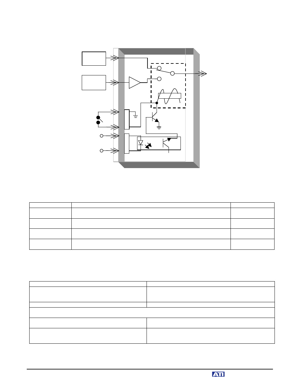
FUNCTIONAL BLOCK DIAGRAM:
INTERNAL CONFIGURATION JUMPERS:
Refer to the following table to change the XLR analog inputs from balanced to unbalanced, and to change the
default 44.1kHz sampling rate to either 32kHz or 48kHz:
FUNCTION
JUMPER SETTING
COMMENTS
XLR Input
Termination
Jumper JM1 grounds the Left XLR inverting input. Jumper JM2 grounds the
right XLR inverting input.
Factory Default:
JM1 and JM2 open
32 kHz Sample
Rate
Jumpers JM3, JM4 and JM5 should be in the 32 position. Jumpers JM6 and
JM7 should be in the 32/48 position.
44.1 kHz Sample
Rate
Jumpers JM3, JM4 and JM5 should be in the 44/48 position. Jumpers JM6
and JM7 should be in the 44 position.
Factory Default
Setting
48 kHz Sample
Rate
Jumpers JM3, JM4 and JM5 should be in the 44/48 position. Jumpers JM6
and JM7 should be in the 32/48 position.
REAR PANEL CONNECTIONS:
Refer to the following table when making rear panel connections to your UADC-1:
AUDIO CONNECTION
DESCRIPTION & COMMENTS
Left & Right XLR Analog Inputs
XLR connectors are Hi-Z, active balanced as supplied from
factory, but can be unbalanced with internal jumper setting
(see above).
Un-Balanced Stereo Analog Input
Via Euroblock connector; connect shield to G terminal.
Connect your source equipment to the appropriate left and right analog inputs. For monaural sources, tie the left and right
inputs together. Be sure to observe correct phasing.
AES XLR Input
For main AES Source input. When used as an EAS insert
switcher, this would normally be the feed from your air chain.
AES XLR Output
This output will provide either the AES audio input or the A-to-
D converted signal from the left and right analog inputs. The
selected input is indicated on the front panel.
Remote Control A
Remote Control B
AES
Output
AES Digital
Audio
Source
Analog
Audio
Source
ADC
+5VDC
+5 to 24VDC
A1
A2
A3
NC
+5VDC
Opto
B1
B2
B3