Rmx-44 audio & control port pin assignments, Pin number, Assignment – Oxmoor RMX-44 User Manual
Page 10: Output b, Figure 3.2: rmx-44 factory setup
13
11
10
9
8
6
5
4
3
14
15
16
17
18
19
20
21
22
23
24
25
1
2
7
12
RMX-44 AUDIO & CONTROL PORT PIN ASSIGNMENTS
Page 8
Input 1
Input 2
Input 3
Input 4
Control
Port
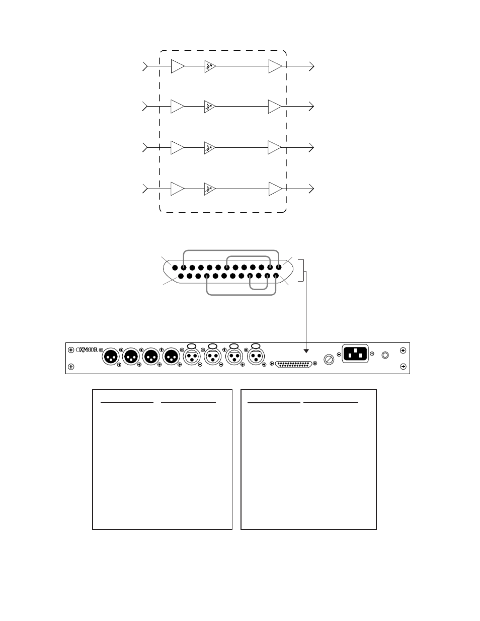
* FACTORY SETUP: The RMX-44 is shipped from the factory with input 1 assigned to output A, input 2 to output B, input 3 to
output C, and input 4 to output D.
Figure 3.3: RMX-44 Audio and Control Port Pin Assignments
Output A
Output C
Output D
Common
Common
Common
Mute
Input 4 to Output B
Input 3 to Output B
Input 2 to Output B
Input 1 to Output B
Input 4 to Output A
Input 3 to Output A
Input 2 to Output A
Input 1 to Output A
+15 VDC
Common
Common
Common
Input 4 to Output D
Input 3 to Output D
Input 2 to Output D
Input 1 to Output D
Input 4 to Output C
Input 3 to Output C
Input 2 to Output C
Input 1 to Output C
+15 VDC
Output B
PIN 2 POSITIVE ON ALL
AUDIO CONNECTIONS
CONTROL PORT
FUSE
POWER
CHASSIS
SERIAL NUMBER
OUTPUT D
OUTPUT C
OUTPUT B
OUTPUT A
INPUT 4
INPUT 3
INPUT 2
INPUT 1
PIN NUMBER
*
1
*
2
3
4
5
6
*
7
8
9
10
11
*
12
13
ASSIGNMENT
ASSIGNMENT
*
14
*
15
16
*
17
18
19
20
21
*
22
23
24
25
PIN NUMBER
14
1
25
13
Figure 3.2: RMX-44 Factory Setup