Ft810ab, Eries, Eceiver – OT Systems FT810AB User Manual
Page 12
FT810AB Series Installation & Operation Manual
12
Signal Ports
OPT - ST (or FC) Optical Connector for fiber cable connection.
VIDEO IN - BNC Video Connectors for video signal inputs.
AUDIO 7-pin Screw Terminal Blocks for audio signal.
5.2 FT810AB Series Receiver
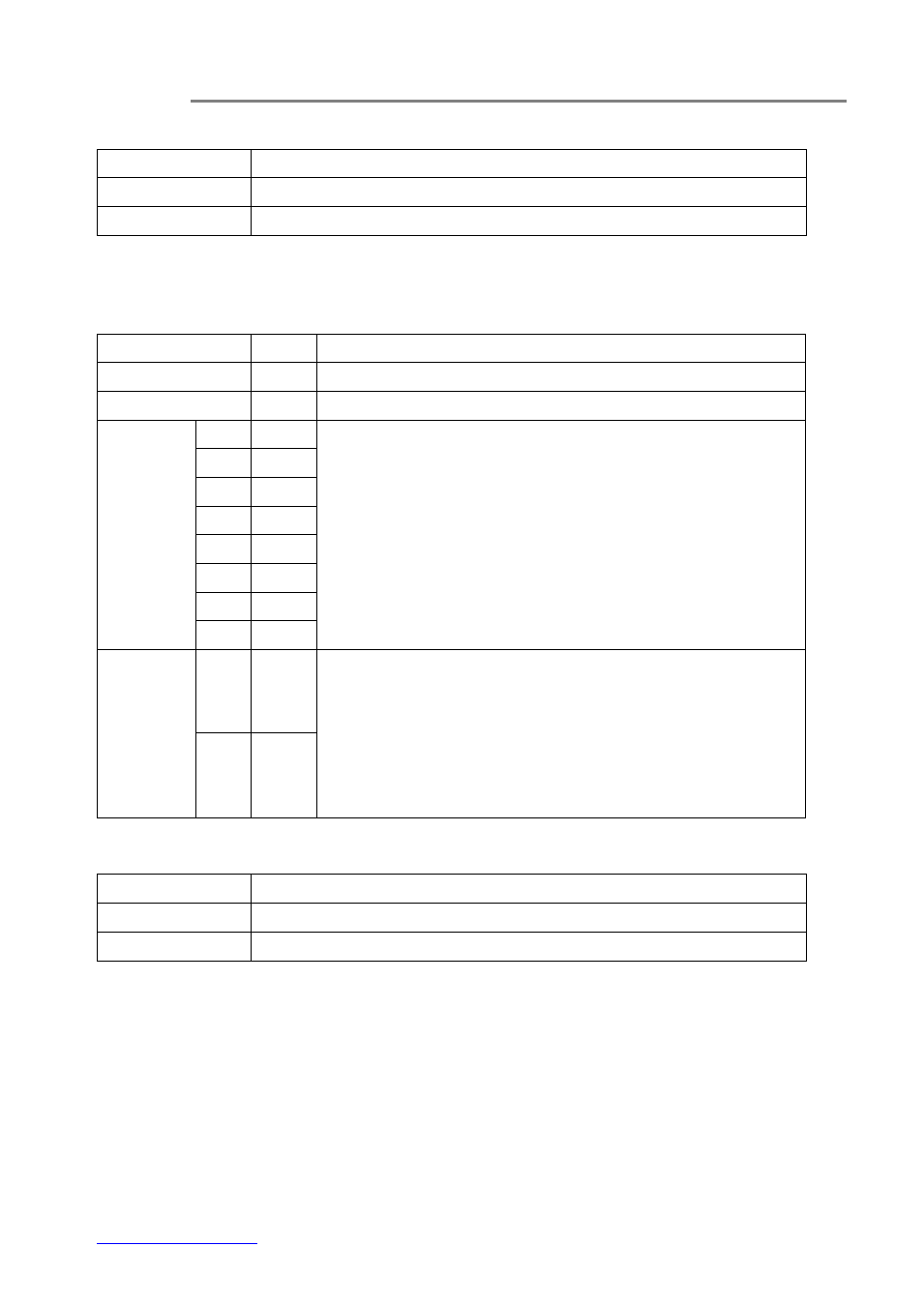
LED Indicators
Indicator
Color
Description
PWR
Red
Lit when power is supplied to the Receiver.
OL
Yellow
Lit when optical signal from transmitter to receiver is active.
VIDEO
OUT /
VOUT
V1
Green
Lit when video signals are received at VIDEO OUT connectors.
V2
Green
V3
Green
V4
Green
V5
Green
V6
Green
V7
Green
V8
Green
AUDIO
IN
Red
a) Each audio channel has a single column of Four LEDs assigned
for displaying the input or output audio levels.
b) The LEDs (Input/Output) are lit in proportion to the signal strength.
c) An increase/decrease of signal level of about 3dB will light up/turn
off an individual LED. All LEDs will go out at or less than -16dBm, and
all are lit when the level attains +6dBm or over.
OUT
Green
Signal Ports
OPT - ST (or FC) Optical Connector for fiber cable connection.
VIDEO OUT - BNC Video Connectors for video signal outputs.
AUDIO - 7-pin Screw Terminal Blocks for audio signal.