Round connection, Operational guides, Ft820db – OT Systems FT820DB User Manual
Page 13: Eries, Ransmitter, 5) operational guides
FT820DB Series Installation & Operation Manual
13
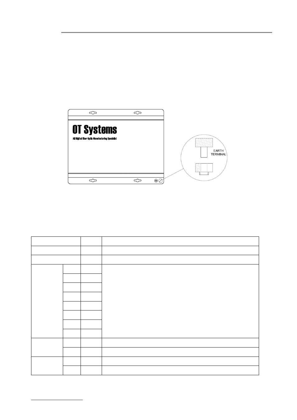
4.4 Ground connection
For enhanced safety to reduce the risks of electrical shock and physical damage, caused by
lightning and other power surges, as well as a connection to the surge suppresion devices in the
product, a screw terminal is provided on the Standalone cabinets (Fig. 4.7). It is highly
recommended that the Standalone unit have good ground connections to the buildings ground in
accordance with the local codes.
Fig. 4.7 Standalone unit earth ground terminal location
(5) Operational Guides
5.1 FT820DB Series Transmitter
LED Indicators
Indicator
Color
Description
PWR
Red
Lit when power is supplied to the Transmitter.
OL
Yellow
Lit when optical signal from receiver to transmitter is active.
VIDEO IN /
VIN
V1
Green
Lit when video signals are fed into the VIDEO IN connectors.
V2
Green
V3
Green
V4
Green
V5
Green
V6
Green
V7
Green
V8
Green
DATA 1
IN
Red
Blinks when input data 1 is available at Tx.
OUT
Green
Blinks when output data 1 is available at Tx.
DATA 2
IN
Red
Blinks when input data 2 is available at Tx.
OUT
Green
Blinks when output data 2 is available at Tx.