Oklahoma Sound #PRC 450 User Manual
Page 4
4
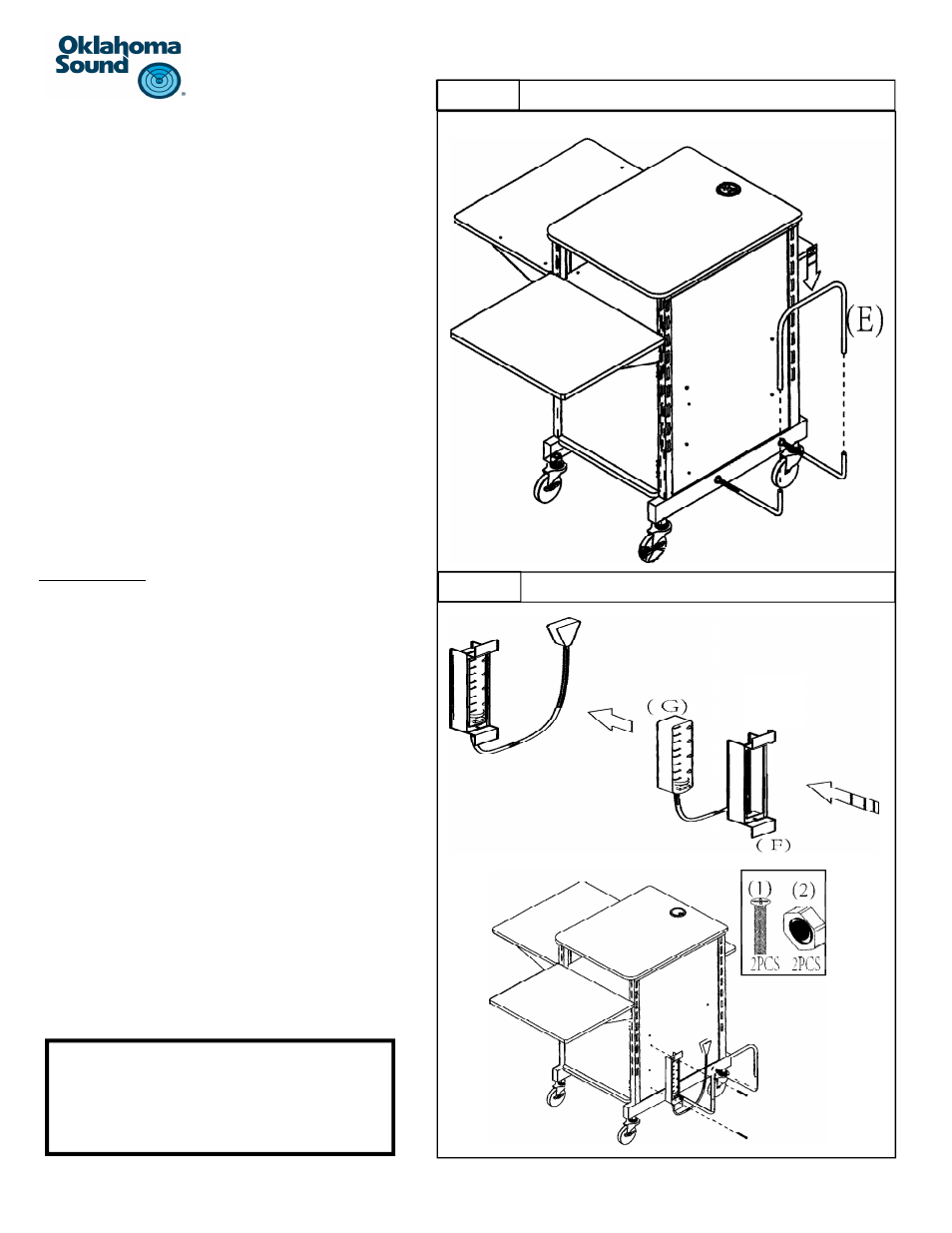
CPU Holder ConƟnued:
a) Once both parts #D are secure in place and the ends
are both poinƟng straight up a 90 degree angle, aƩach
the “U” shaped part #E as shown.
b) Align the two open ends of part #E over the two ends
of both parts #D. The ends of part #E will slip over part
#D.
c) Gently push part #E all the way down.
Power Assembly
a) IdenƟfy the metal winder part #F and the power strip
part #G.
b) Part #F will slip over the power strip with only the
switch and the outlets accessible with the cord of the
power strip hanging out from the boƩom as shown.
c) To aƩach the enƟre power assembly to the unit, begin
by locaƟng the two holes on part #F, one on top and
one on boƩom.
d) These two holes will align with the two holes on the
side wall of panel #A as shown in the illustraƟon.
e) Once the two holes on part #F are aligned with the
holes on the side wall, use the two screws part #1 and
thread them through the hole on the metal winder and
through the side panel.
f)
Once the screws are completely threaded through, use
two nuts part #2 and secure the bolt from the inside of
the cabinet.
Step 3
STEP 4
CongratulaƟons!!! Your PRC 450 is
now fully assembled!!