Mc2 contr ols at a glance – Joemeek MC2 Stereo Compressor User Manual
Page 3
5
4
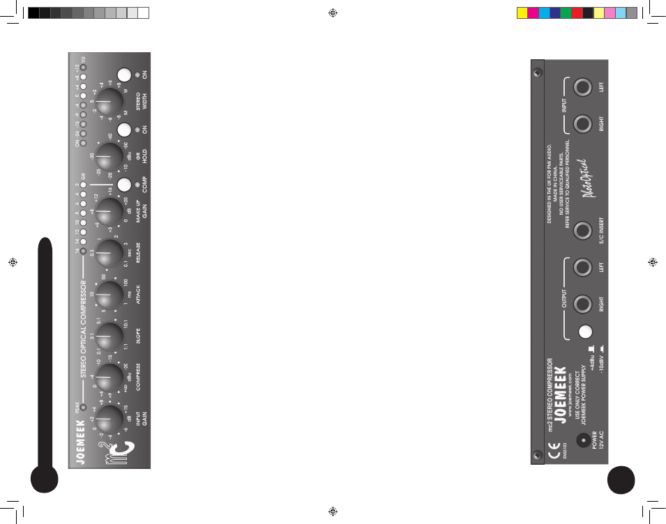
INPUT
GAIN
–
sets
the
amount
of
audio
amplification.
Too
little
gain
and
the
resulting
sound
will
be
too
quiet;
too
much
and
the
signal
could
become
distorted.
PEAK LED
– lights 6dB below clipping.
COMPRESS
–
sets
the
level
of
signal
(or
“Threshold”)
above
which
the
signal starts to be compressed.
SLOPE
– sets the compression ratio applied to signals above threshold.
A
TT
ACK
–
sets
how
quickly
the
compressor
responds
to
peaks
above
threshold.
RELEASE
–
sets
the
time
taken
for
the
signal
to
return
to
its
normal
size
after
compression.
In
general,
the
longer
the
time,
the
less
obvious
the
compression.
MAKE UP
GAIN
– restores the level of the signal after compression.
COMP
– switch turns the compressor on.
The LED lights when active.
GR
HOLD
–
freezes
Gain Reduction at
a
constant
level during gaps in the
programme material (ie: prevents the compressor gain rising).
GR
Hold
ON
–
switch
turns
the
GR
Hold
function
on.
The
LED
lights
when
active and changes color to indicate Hold status.
STEREO
WIDTH
–
varies
the
perceived
with
of
the
programme
material
from Mono, to normal Stereo, to extra Wide.
Stereo
W
idth
ON
–
switch
turns
the
Stereo
Width
function
on.
The
LED
lights when active.
VU
METER
–
8-Led
bargraph
shows
the
output
signal
level
in
dB
at
any given moment.
GR
METER
–
8-Led
bargraph
indicates
the
amount
of
gain
reduction
in dB, which is taking place at any given moment.
INPUTS
– Balanced line level inputs on 1/4”
TRS jacks.
S/C
INSERT
–
unbalanced
“Send
and
Return”
jack
allows
you
to
patch
other pieces of equipment, into the compressor
’s control circuitry
OUTPUTS
– Balanced line level outputs on 1/4”
TRS jacks.
+4dBu/-10dBv
–
switch
selects
the
operating
level
of
the
1/4”
jack
outputs,
either
to
the
professional
+4dBu
level,
or
to
the
-10dBv
semi-
pro level.
mc2
Contr
ols
at
a
Glance
mc2 manual.indd 6-7
3/20/06 12:51:40 PM