Datapath dL8 User Manual
Page 8
8
Fig. 6
The main control dialog is divided into the following groups:
Connection
DVI-D Input
EDID Prefered Mode
DVI-I Outputs
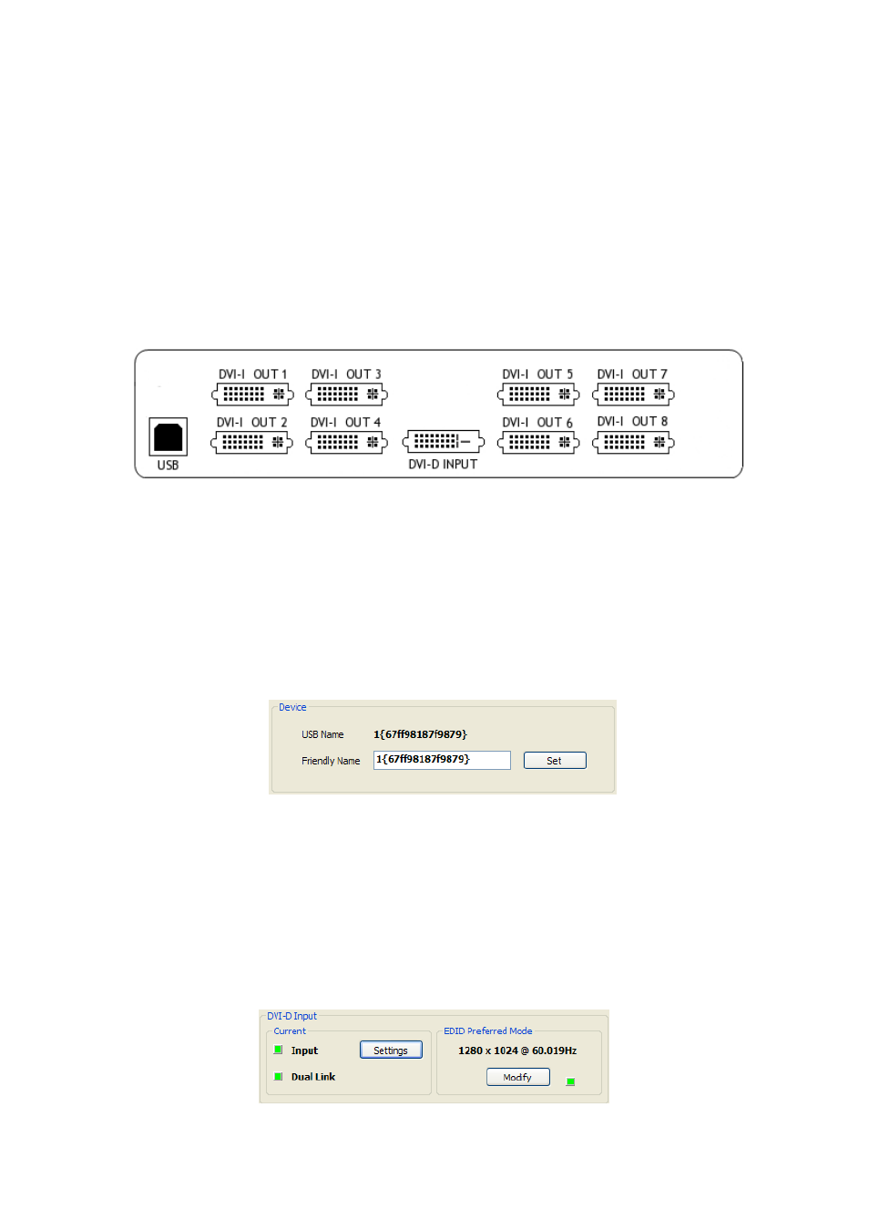
Connection Diagram
The connection diagram displays a schematic view of the rear panel of the dL8 to assist in identifying the
connectors.
DVI-D Input
The DVI-D Input group indicates if an input is currently being captured and if the input is Dual Link. It also
displays the preferred mode that has been programmed into the dL8’s EDID. Use the Modify button to
update the EDID. The small square to the left of Input and Dual Link indicates:
• Green – A valid input is connected to the dL8. The input connected is Dual Link
• Grey – A valid input is not connected. Dual Link input not detected.
Device
The unique USB device name that is connected is displayed in the Device group. It is possible to associate
a more user friendly name such as “Main Video Wall”. The friendly name is stored in non-volatile storage
on the dL8 and can to help identify the device during future configurations. Specific devices connected to
your PC can be selected using the Select Device.. command on the File Menu. The dL8’s will be listed by
the USB Device or by a previously configured friendly name.
Fig. 7
Fig.8