Basic information, Front and rear panel layout, Front panel layout – Dataman 520 Series User Manual
Page 9: Dataman 770 series rear panel layout
Spectrum analyzer
User’s guide
2. Basic information
2.1. Front and rear panel layout
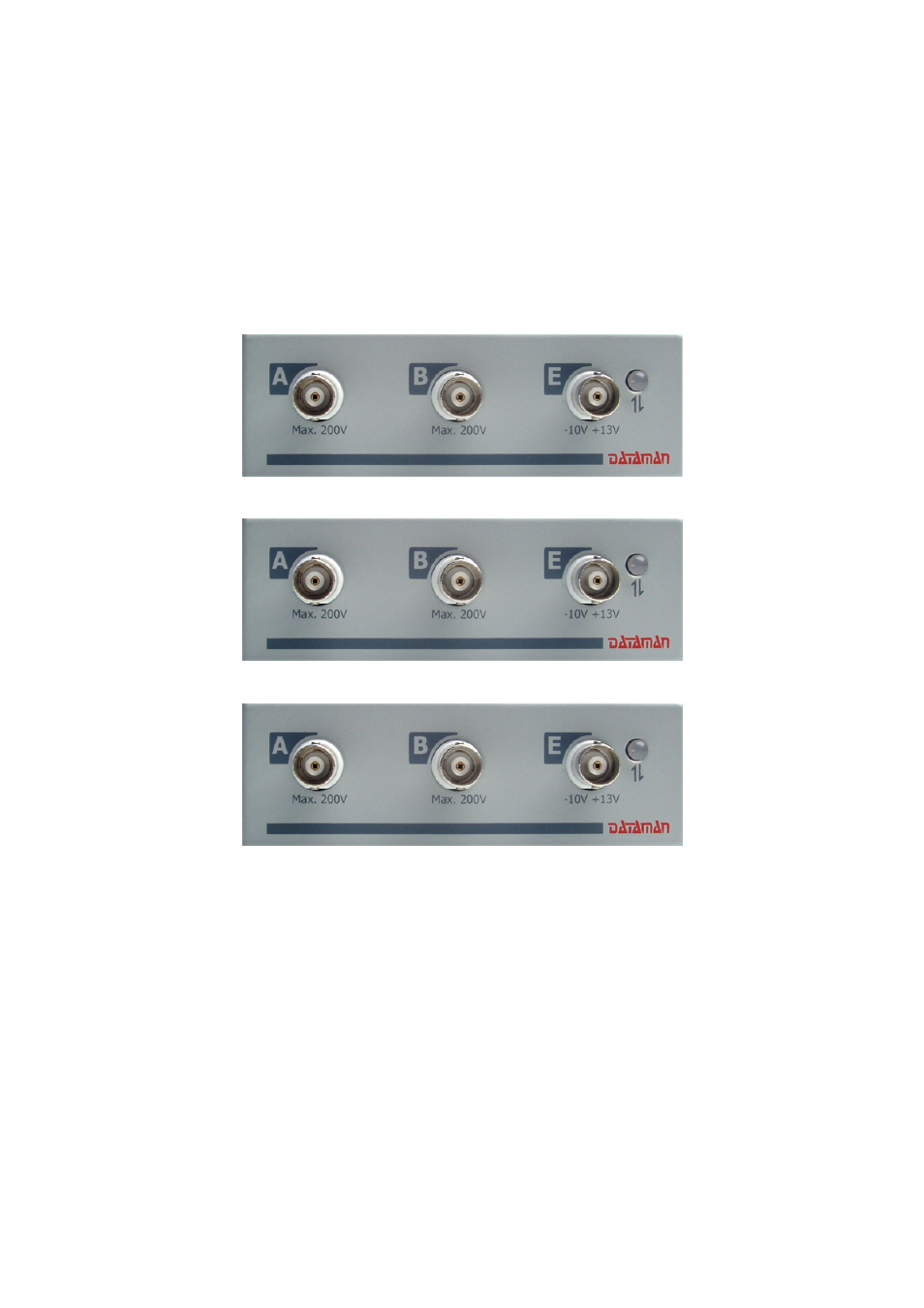
2.1.1. Front panel layout
Channel A, channel B, external synchronization input / compensation generator
output and an LED are accessible on the front panel.
Fig. 2.1.1.1. – Front panel of the DATAMAN 570 series oscilloscope
Fig. 2.1.1.2. – Front panel of the DATAMAN 520 series oscilloscope
Fig. 2.1.1.3. – Front panel of the DATAMAN 770 series oscilloscope
If the LED color is:
- green, the device is configured and there is no communication with a
computer at this time
- orange, the device is communicating with a computer
- red, device is powered, but not configured
2.1.2. DATAMAN 770 series rear panel layout
Two connectors are available on the rear panel.
- USB connector for communication with computer (used for supplying device with
power as well)
- banana jack (4mm) for optional ground connection. This connector is connected to
the ground (chassis) of the host computer and should be connected to the environment
- 9 -