Controller settings – d&b Vi8 User Manual
Page 7
Selecting the respective V8 or V12 setup enables up to two Vi8/
Vi12 cabinets to be driven by the respective channel of the
amplifier.
"Arc" and "Line" setups
The selection of "Arc" or "Line" depends on the curvature of the
array. Both setups may be used within one array.
The "Arc" setup is intended for line array loudspeakers when used
in curved array sections.
The "Line" setup is used for long throw array sections with three or
more consecutive splay settings of 0°, 1° or 2°. Compared to the
"Arc" setup, the mid/-high range is reduced to compensate for the
extended nearfield.
The transition from "Line" to "Arc" configuration within the array is
made according to the splay progression but may allow for certain
deviations due to the wiring of the cabinets in groups of up to two.
2.3.1. Controller settings
For acoustic adjustment the functions CUT, CPL and HFC can be
selected.
CUT circuit
Set to CUT, the low frequency level of the cabinets is reduced. The
Vi8/Vi12 array is now configured for use with the d&b Vi-SUB or
J-SUB subwoofers.
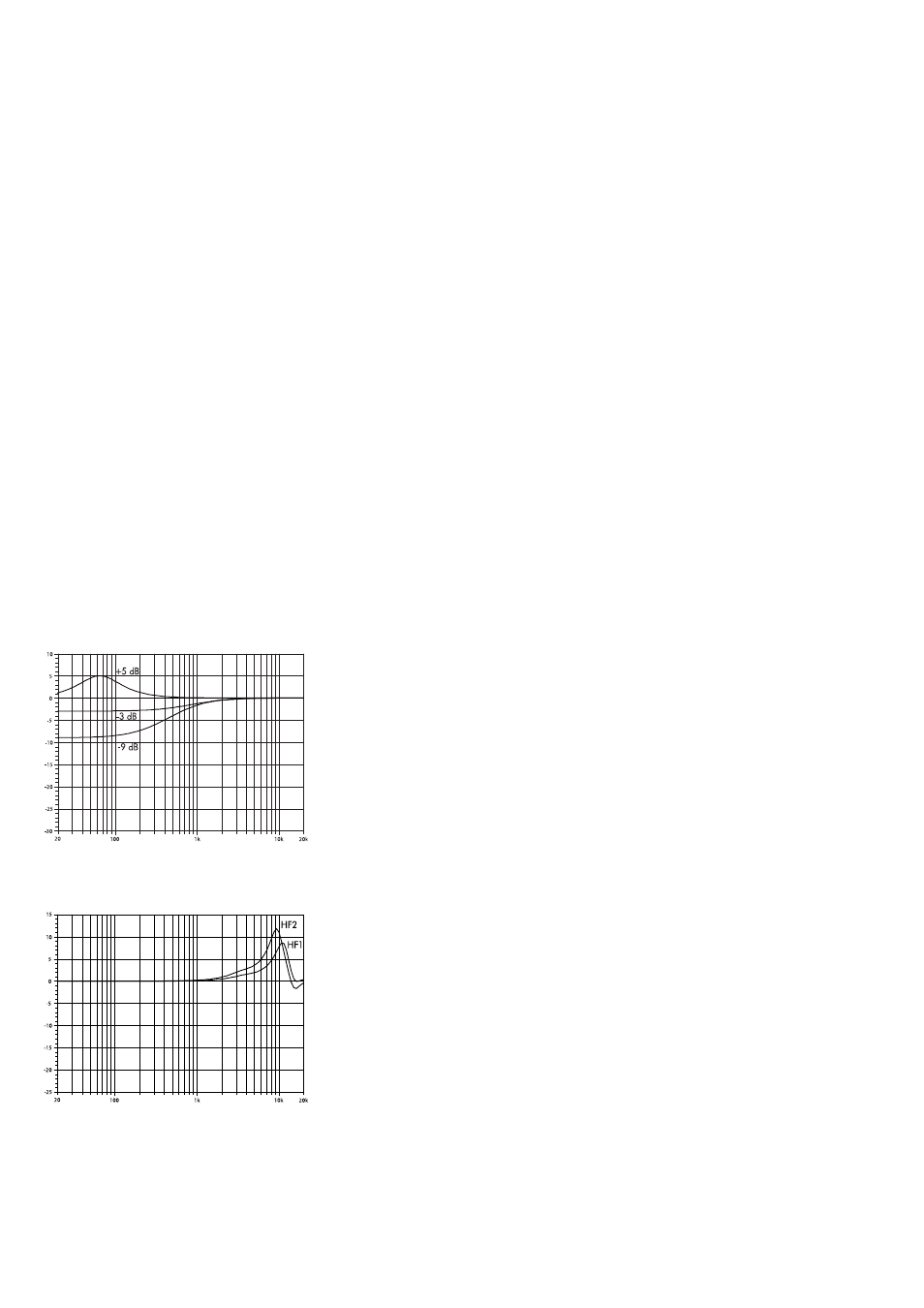
CPL circuit
The CPL (Coupling) circuit compensates for coupling effects
between the cabinets of an array. CPL begins gradually around
2 kHz, with the maximum attenuation below 100 Hz. As coupling
effects increase with the length of the line array, the CPL circuit can
be set to dB attenuation values between 0 and –9. With higher
attenuation values the corner frequency of the filter shifts towards
lower values.
Positive CPL values create an adjustable low frequency boost (0 to
+5 dB) and can be set when the system is used in full range mode
without subwoofers.
Note: Make sure that all cabinets within the line array are
operated with the same CPL setting.
HFC circuit
Selecting the HFC (High Frequency Compensation) circuit
compensates for loss of high frequency energy due to absorption
in air when loudspeakers are used to cover far field listening
positions.
The HFC circuit has two settings (HFC1, HFC2) for different
distance ranges the cabinets have to cover. The settings should be
used selectively, only for those cabinets covering the respective
distances, HFC1 for distances larger than 30 m (100 ft) and HFC2
for distances larger than 60 m (200 ft).
The compensation is adjusted for a typical relative humidity of
40 %. With lower humidity the absorption by air increases
therefore the distances where the respective HFC setting provides a
correct equalization are shorter than indicated above.
Fig. 3: Frequency response correction of CPL circuit
Fig. 4: Frequency response correction of HFC circuit
d&b Vi8/Vi12 Manual (1.2 EN)
7