Connections, Operation, Controller settings – d&b V8 User Manual
Page 6
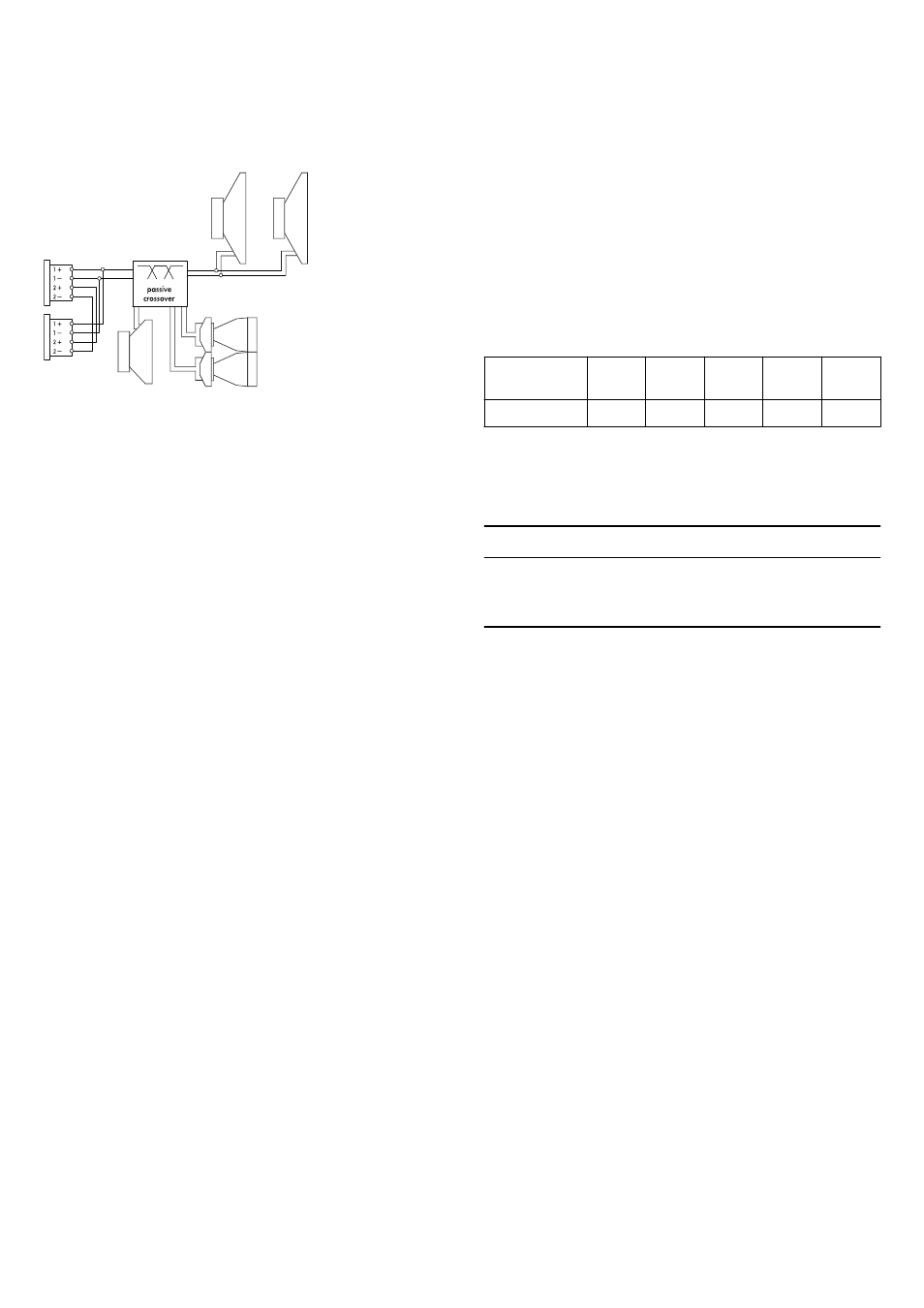
2.2. Connections
The cabinets are fitted with a pair of 4-pin connectors. All four pins
of both connectors are wired in parallel. The V8 and V12
loudspeakers use the pin assignments 1+/1–. Pins 2+/2– are
designated to active subwoofers. Using the male connector as the
input, the female connector allows for direct connection to a
second cabinet.
The cabinets can be supplied with EP5 connectors as an option.
Pin equivalents of the connector options are listed in the table
below.
NL4
NLT4 F/M
1+
1–
2+
2–
n.a.
EP5
1
2
3
4
5
2.3. Operation
NOTICE!
Only operate d&b loudspeakers with a correctly configured d&b
amplifier, otherwise there is a risk of damaging the loudspeaker
components.
The applicable amplifiers provides two setups ("Arc" or "Line") for
the V8 and V12 loudspeakers. These are available in Dual
Channel or Mix TOP/SUB mode.
Selecting the respective V8 or V12 setup enables up to two
V8/V12 cabinets to be driven by the respective channel of the
amplifier.
"Arc" and "Line" setups
The selection of "Arc" or "Line" depends on the curvature of the
array. Both setups may be used within one array.
The "Arc" setup is intended for line array loudspeakers when used
in curved array sections.
The "Line" setup is used for long throw array sections with three or
more consecutive splay settings of 0°, 1° or 2°. Compared to the
"Arc" setup, the mid/-high range is reduced to compensate for the
extended nearfield.
The transition from "Line" to "Arc" configuration within the array is
made according to the splay progression but may allow for certain
deviations due to the wiring of the cabinets in groups of up to two.
2.3.1. Controller settings
For acoustic adjustment the functions CUT, CPL and HFC can be
selected.
CUT circuit
Set to CUT, the low frequency level of the cabinets is reduced. The
V8/V12 array is now configured for use with the d&b V-SUB or
J-SUB subwoofers.
Fig. 2: Connector wiring
d&b V8/V12 Manual (1.6 EN)
6