Connections, Operation, Controller settings – d&b V-SUB User Manual
Page 6
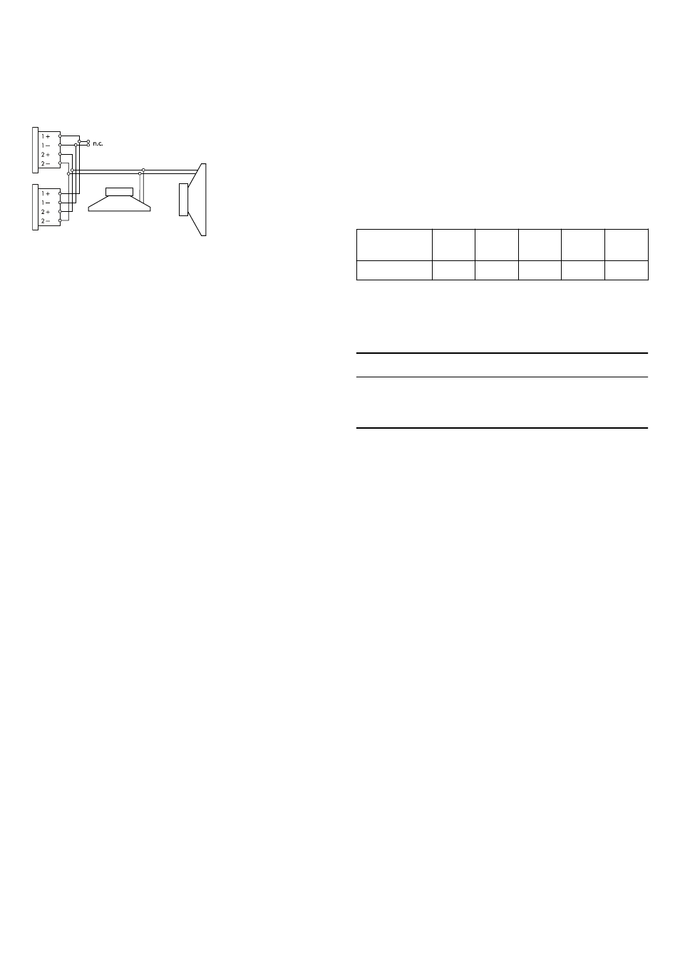
2.2. Connections
The cabinet is fitted with a pair of 4-pin connectors. All four pins of
both connectors are wired in parallel. The V-SUB uses the pin
assignments 2+/2–. Pins 1+/1– are designated to the V8 or V12
loudspeakers. Using the male connector as the input, the female
connector allows for direct connection to a second cabinet.
The cabinet can be supplied with EP5 connectors as an option. Pin
equivalents of the connector options are listed in the table below.
NL4
NLT4 F/M
1+
1–
2+
2–
n.a.
EP5
1
2
3
4
5
2.3. Operation
NOTICE!
Only operate d&b loudspeakers with a correctly configured d&b
amplifier, otherwise there is a risk of damaging the loudspeaker
components.
Select the controller setup V-SUB.
Within applicable amplifiers it is available in Dual Channel or Mix
TOP/SUB mode.
Selecting the V-SUB setup enables up to two V-SUB loudspeakers
to be driven by the respective amplifier channel.
2.3.1. Controller settings
For acoustic adjustment the 100 Hz function can be selected.
100 Hz circuit
If the 100 Hz circuit is selected, the upper operating frequency of
the system is reduced from 115 Hz to 95 Hz.
It can be used when actively driven V-SUB subwoofers are used to
supplement V-Series cabinets operated in full range mode. The
100 Hz mode can also be used to compensate for the effect of
close coupling between the V-SUB and V-Series cabinets operated
in CUT mode. With T-Series cabinets the standard mode is
recommended.
Fig. 3: Connector wiring
d&b V-SUB Manual (1.3 EN)
6