Connections – d&b 27S-SUB User Manual
Page 6
Vertical arrays are supported using the Z5414 Flying bar xA and
the Z5413 Flying bar connector plates xA. For approved
configurations as well as safety and mounting instructions, refer to
the respective rigging manual.
Cabinet options
The weather resistant version (WR) is suitable for outdoor use
(IP34, vertical aiming up to 0°). The cabinets have an impact and
weather protected black PCP (Polyurea Cabinet Protection) finish.
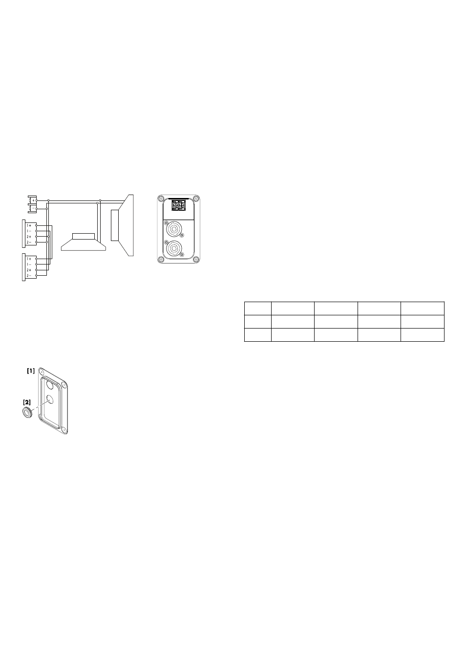
2.2. Connections
The cabinets are fitted with a pair of NL4 connectors and a two
pole screw terminal block (ST). All four pins of both NL4
connectors are wired in parallel. The cabinets use the pin
assignments 2+/2–. Pins 1+/1– are designated to full range
cabinets.
Cabinets with the weather resistant option (WR) are equipped with
a fixed input cable (PG type, H07-RN-F, 2 x 2.5 mm
2
(AWG 13),
standard length 5.5 m (18 ft).
Pin equivalents of the applicable connector options are listed in the
table below.
NL4
1+
1–
2+
2–
ST
n.a.
n.a.
+
–
PG
n.a.
n.a.
Brown (+)
Blue (–)
Fixed cable connection
The 27S-SUB and 27A-SUB loudspeakers are each supplied with
a cover plate
[1] and a rubber grommet feed through [2]. For
indoor operation, these items can be used to hide the connector
panel, if required. For unprotected outdoor operation, the
connector panel must be covered, i.e. both items must be used to
achieve an IP degree of protection of IP34.
To install the fixed cable connection, proceed as follows:
Tools required: Philips screw driver (#PH2).
1. Prepare the rubber grommet and the connection cable.
2. Remove the knockout opening in the cover plate and attach
the rubber grommet correspondingly.
3. Insert the connection cable through the rubber grommet and
connect the cable wires to the screw terminal.
Þ Observe the correct polarity!
4. Undo the four screws of the connector panel.
5. Push the cover plate towards the connector panel until it fits
into place.
6. Finally fix the cover plate together with the connector panel
using the four screws.
Fig. 3: Connector wiring
Fig. 4: Cover plate and rubber grommet
d&b 27S-SUB/27A-SUB Manual (1.2 EN)
6