Direct - on - line starters, Installation and maintenance instruction for, Safety installation 1 – Crompton Controls 3DL07 --I User Manual
Page 2: Important general
Crompton Components Ltd
Monckton Road,
Wakefield,
West Yorkshire WF2 7AL
Tel: (01924)368251
Fax: (01924)367274
E-mail: [email protected]
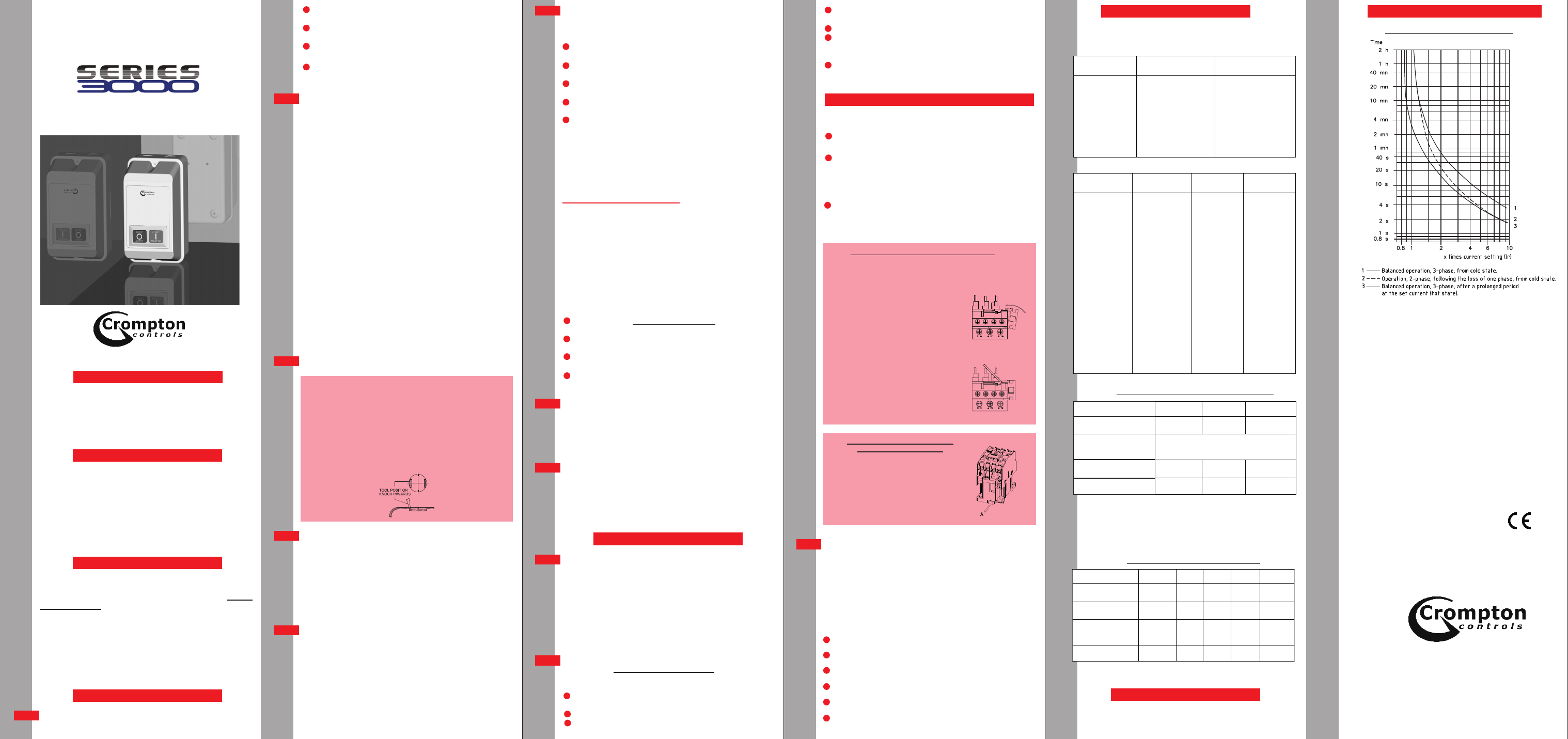
OVERLOAD CHARACTERISTICS
All information contained in this publication is, as far as
possible, correct at the time of going to print. however, due
to our policy of continued improvement, we reserve the
right to alter specifications without prior notice.
All goods are guaranteed for two years from date of
purchase. This does not affect the statutory rights of
user.
INSTALLATION AND
MAINTENANCE INSTRUCTION
FOR
DIRECT - ON - LINE STARTERS
IMPORTANT
GENERAL
SAFETY
INSTALLATION
1
IMPORTANT
This leaflet carries important information in respect of
Health and Safety at Work and should remain with the
starter at all times. Extra copies, if required, are available
from the address shown.
Crompton Controls 'Series 3000' starters are
manufactured to British standards BSEN60947-Pt4-Sec 1.
BSEN60529-1992 and to IEC947-4-1. Crompton Controls
manufacture the starters under a Quality Management
System registered to ISO 9001:2008. All starters give degree
of protection IP 55 (minimum) and are suitable for use up
to an altitude of 2000 meters above sea level and for
operation in ambient temperatures of -5 C to +40 C
All electrical equipment for operating on low voltages
contain devices which are capable of causing serious
or fatal injuries.
Any person who is involved on installation or
maintenance of this equipment should be fully
competent to carry out this work. Such persons should
be familiar with the Health and Safety at Work Act 1974
and the Electricity at Work Regulations 1989. Persons
responsible for installation should also have a working
knowledge of the IEE Wiring Regulations.
PREPARATION The following points should be checked
before commencing the installation of the starter.
KNOCKOUTS: WHEN REMOVING KNOCKOUTS
CARE MUST BE TAKEN NOT TO DISTORT THE SIDE OF
THE ENCLOSURE.
Single knockouts are designed to be removed INWARDS
with a twisting/rocking action by applying a small chisel or
similar tool to the extreme edge of the knoclout at 90 to
the retaining lugs and tapping with a hammer. Move tool
across to the other edge and repeat process until knockout
is released.
o
o
o
That the equipment is suitable for the voltage of the
system.
That the setting range of the overload unit is suitable
for the motor involved.
That the starter is suitable for the operating
environment.
General inspection of the starter should be carried out
to make sure that there has been no damage caused
by transportation or storage.
M o d e r n h i g h -
performance contactors rely on the low inertia of their
moving parts to achieve this performance. Because of this,
any knocks or vibration can seriously affect the
performance of these starters. It is essential, therefore, that
the starter should be mounted away from any vibration
and in a position where it is extremely unlikely that the
starter will receive any knocks.
Although the starters are protected to IP55 thereby
restricting the ingress of dust and moisture, the starter
should be mounted in such a manner as to minimise the
effects of dust and moisture. In particular, the effects of
condensation occurring within the starter should be
minimised.
It is essential, where dust and moisture are present, to take
particular care when fixing the starter to the mounting
surface and when making conduit connections to ensure
that these areas are properly sealed.
When the mounting position has been decided, it may be
advantageous to remove the starter interior from the
enclosure to remove the knockouts, fasten the base to the
mounting area and to complete the external wiring.
Where the only connection to the cover is an earth
connection, this should be disconnected. Do not allow the
cover to hang on the earth lead as this may affect earth
continuity.
The starters are fitted with single
knockouts and the methods of removal are shown below:-
All wiring connected to the starter should be in
accordance with the latest edition of The Institute of
Electrical Engineers Regulations for Electrical Installation.
It is essential that earthing of the starter is carried out in a
proper manner. This is preferably done by the use of a
separate earth conductor which also connects through to
the motor. We do not recommend earthing via mounting
points or conduit fittings, as these can become corroded
and affect earth continuity.
The starter, cabling and the
motor should be protected against short circuit conditions
by adequately rated fuses or circuit breakers.
The overload unit fitted to the starter should be set to
correspond to the full load current of the motor,
Some starters may be fitted with Thermistor
Protection units used in conjuction with thermistors fitted
in the motor to give over-temperature protection. The
protection given in this case is dependent on the
thermistors fitted to the motor and consequently
adjustment of this unit is not required.
.
.
.
L O C AT I O N A N D M O U N T I N G
KNOCKOUTS
WIRING
CIRCUIT PROTECTION
NOTE: -
FINAL CHECKING AND TESTING
OPERATIONAL PROBLEMS
FAULTY OPERATION
GENERAL
CHECKING
Before applying
power to the starter, it is advisable to carry out the
following checks:-
Check all mechanical fixings to ensure that they are
tight.
Check all terminals to ensure that they are tight
especially the earth connection.
Check that the moving contact carriage of all contactors
are free to operate.
Set any timers which may be included in the starter to
the approximate time required.
Ensure that the earth connection between base and
cover is in place.
In the interest of safety, we recommend that the cover
of the starter is secured in place before applying power
to the starter and that testing should only be carried
out in this condition. Any adjustments which may be
necessary should be carried out with the supply isolated.
As a general rule, this equipment should be
disconnected from the supply before carrying out work of
any nature. However, there may be times, particularly
during servicing when it is necessary to work on the
equipment with the supply connected (e.g. checking
voltages and currents).
.
Although these starters have been designed to afford
finger protection, it is essential to observe the following
precautions before working on the starters with the
supply connected:-
Ensure that it is absolutely necessary to work on the
equipment whilst in a live condition.
Ensure that you are fully aware of the layout of the
starter and where to expect live connections.
Ensure that you are within sight of other people who
could come to your aid if necessary.
Ensure that any tools requipment used are suitable
for working on live equipment.
Should you have any
doubts regarding operational problems, application of
starters or any technical queries, our technical staff are
available to advise. This advice is available via our field
Sales Engineers or via our Head Office as shown on this
leaflet.
In the unlikely event of faulty
operation, please check the complete system. If you are
certain that the fault lies in the starter, contact your
supplier Who will negotiate any warranty claim with
Crompton Controls. In The event of any difficulties, you
may contact Crompton Controls direct at the address
shown on this leaflet.
Crompton controls 'Series 3000' starters are
designed to give long trouble-free operation. The life of
the starter will, of course, depend on the duty to which it is
subjected. The operational (electrical) life at full current
rating of the contactors is designed to be 500,000
operations .
However, as with any equipment, it is advisable to carry out
routine checks to ensure that there are no problems
developing which could cause failure.
Before carrying out routine checks, it is
important to observe safety precautions printed in bold
type under installation.
The following checks are advisable:-
Check all screws, fixings and terminals to ensure that
they are tight.
Check all moving parts for ease of operation.
Examine all wiring for damaged insulation.
.
.
.
.
Check cover seals and conduit entries to ensure that
sealing is still intact.
Check all earth connections.
Check visually for signs of overheating or arc damage.
Any such damage should be investigated and remedied
without delay.
Check for ingress of dust and/or moisture which could
adversely affect the equipment.
When fitting an overload relay into this starter the
following procedure should be observed.
Unscrew the Contactor male terminal screws until the
clamps are fully open.
Attach the start push button contact block to the
overload as shown in the sketch below.
When correctly located only a very light force is
required to clip the block into position.
Align the overload pins according to the contactor
selection. Fit the overload pins into the contactor
terminals and tighten the terminal screws, ensuring
that all three pins are underneath the terminal clamps.
Most parts of the starters are not regarded as
serviceable items and therefore, in general, complete
components are required. The following list gives a guide
to the parts which are available and the information
required when ordering replacement parts.
In order to ensure that the correct parts are supplied
please quote the details given on the starter rating plate
and the details given on the component rating plate along
with the information shown alongside the description.
.
.
.
.
.
.
.
.
.
SPARES
1
2
3
4
3
6
4
7
5
a
b
c
d
e
8
a
b
c
d
MAINTENANCE
WORKING ON LIVE EQUIPMENT
OVERLOAD RELAY FITTING INSTRUCTIONS
1
4
5
7
6
TECHNICAL DETAILS –
TIMERS, THERMISTOR PROTECTION UNITS
See separate booklet Ref: - BCC 2069 (Timers)
Ref: - BCC 2072 (Thermistors)
OVERLOAD RELAY DETAILS
PARAMETER
CR09-25
CR32
CR40-63
Aux. Contact rating
415V(AC15)
2.5
2.5
2.5
Ambient
Temperature
Compensation
-40ºC to +60ºC
Max. Cable size:
Main Terminals mm²
2x4
2x6
2x16
Aux. Terminals mm²
2x2.5
2x2.5
2x2.5
1
2
CONTACTOR DETAILS
PARAMETER
CC09~12
CC18
CC25
CC32
CC40~65
Coil Inrush VA
Closed VA
60
7
60
7
90
7.5
90
7.5
200
20
Aux. Contact 415V
rating (AC15)A
2.5
2.5
2.5
2.5
2.5
Max. Cable size:
Main Terminals
mm²
2x4
2x6
2x6
2x10
2x16
Aux. Terminals mm²
2x2.5
2x2.5
2x2.5
2x2.5
2x2.5
Technical Details - Contactors
WARRANTY
2
Technical Details - Overload Relays
3
Use narrow bladed screwdriver to
move clip in direction of arrow 'A' as
shown on drawing right. whilst lifting
the unit from the mounting rail . This can
be done with the overload unit fitted to
the contactor if in doubt remove
overload unit from contactor ,to
improve access to the clip.
REMOVAL OF CONTACTORS FROM
DIN FORM MOUNTING RAIL
The start contact is clipped into position adjacent to terminal
96 on the overload relay.
ASSEMBLY:
REMOVAL:
Locate contact on lower right hand
corner of overload relay moulding
and rotate anti - clockwise until
firmly clipped into place
Place small screwdrier blade
under leading edge of clip and
lever off
ASSEMBLY/REMOVAL OF START CONTACT
Contactors – Voltage and frequency.
Contactor coils – Voltage and frequency.
Overload Units – Current range.
Mechanical interlocks.
Timers – Voltage, Frequency and Timing Range.
Isolators.
f
e
d
c
b
a
2
3
3
2
1
FUSE RATING FOR TYPE-2 CO-ORDINATION
O/L TYPE
RANGE
MAX FUSE
(FAST)
MAX FUSE
(SLOW)
CR09/0.25
0.16 – 0.25A
1
0.5
CR09/0.4
0.25 - 0.4A
2
1
CR09/0.63
0.4 – 0.63A
2
1
CR09/1
0.63 – 1A
4
2
CR09/1.6
1 – 1.6A
4
2
CR09/2.5
1.6 – 2.5A
6
4
CR09/4
2.5 – 4A
10
6
CR09/6
4 – 6A
16
8
CR09/8
5.5 – 8A
20
12
CR09/10
7 – 10A
20
12
CR12/13
10 – 13A
25
16
CR16/18
13 – 18A
32
20
CR25/25
18 – 25A
50
25
CR32/32
23 - 32A
63
40
CR32/40
28 - 40A
63
40
CR63/50
38 – 50A
100
63
CR63/57
48 – 57A
100
63
CR63/66
57 – 66A
100
63
RATINGS (AC3)-AMPS
DIRECT ON LINE- TYPE 3DL
STARTER MAXIMUM
TECHNICAL INFORMATION
STARTER REF
3 PHASE
220V
415V
3DL1***
12
12
3DL2***
18
18
3DL3***
25
25
3DL4***
32
32
3DLA5***
40
40
3DL5***
60
60
3DL6***
65
65
1 PHASE
240V
480V
12
9
18
14
25
19
32
24
40
30
60
45
65
49
CR09 TO CR80 TRIPPING CURVE
- 3DL07 --S 3DL07 –F 3DL08 --I 3DL08 --S 3DL08 –F 3DL09 --I 3DL09 --S 3DL09 –F 3DL1 --F 3DL1 --I 3DL1- -S 3DL10 --I 3DL10 --S 3DL10 –F 3DL11 --I 3DL11 --S 3DL11 –F 3DL12 --I 3DL12 --S 3DL12 –F 3DL2 --I 3DL2 --S 3DL2 –F 3DL3 --I 3DL3 --S 3DL3 –F 3DL4 --I 3DL4 --S 3DL4 –F 3DL5 --I 3DL5 --S 3DL5 –F 3DL6 --I 3DL6 --S 3DL6 –F 3DLA5 --I 3DLA5 --S 3DLA5 –F 3EX1- -S