Crompton Controls 3DS1- -I User Manual
Page 2
Unscrew the Contactor male terminal screws until the
clamps are fully open.
Attach the start push button contact block to the
overload as shown in the sketch below.
When correctly located only a very light force is
required to clip the block into position.
Align the overload pins according to the contactor
selection. Fit the overload pins into the contactor
terminals and tighten the terminal screws, ensuring
that all three pins are underneath the terminal clamps.
Most parts of the starters are not regarded as
serviceable items and therefore, in general, complete
components are required. The following list gives a guide
to the parts which are available and the information
required when ordering replacement parts.
In order to ensure that the correct parts are supplied
please quote the details given on the starter rating plate
and the details given on the component rating plate along
with the information shown alongside the description.
.
.
.
.
.
SPARES
Contactors – Voltage and frequency.
Contactor coils – Voltage and frequency.
Overload Units – Current range.
Mechanical interlocks.
Timers – Voltage, Frequency and Timing Range.
Isolators.
f
e
d
c
b
a
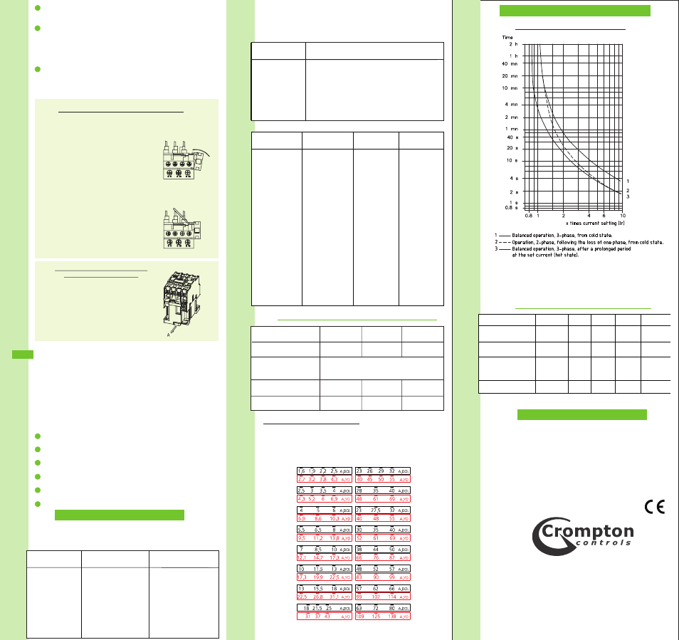
1
2
3
Use narrow bladed screwdriver to
move clip in direction of arrow 'A' as
shown on drawing right, whilst lifting
the unit from the mounting rail . This can
be done with the overload unit fitted to
the contactor if in doubt remove
o v e r l o a d u n i t f r o m c o n t a c t o r, t o
improve access to the clip.
REMOVAL OF CONTACTORS FROM
DIN FORM MOUNTING RAIL
The start contact is clipped into position adjacent to terminal
96 on the overload relay.
ASSEMBLY:
REMOVAL:
Locate contact on lower right hand
corner of overload relay moulding
and rotate anti - clockwise until
firmly clipped into place
Place small screwdrier blade
under leading edge of clip and
lever off
ASSEMBLY/REMOVAL OF START CONTACT
3
3
TECHNICAL DETAILS - OVERLOAD RELAYS
TECHNICAL INFORMATION
TECHNICAL INFORMATION
FUSE RATING FOR TYPE-2 CO-ORDINATION
O/L TYPE
RANGE
MAX FUSE
(FAST)
MAX FUSE
(SLOW)
CR09/0.25
0.16 – 0.25A
1
0.5
CR09/0.4
0.25 - 0.4A
2
1
CR09/0.63
0.4 – 0.63A
2
1
CR09/1
0.63 – 1A
4
2
CR09/1.6
1 – 1.6A
4
2
CR09/2.5
1.6 – 2.5A
6
4
CR09/4
2.5 – 4A
10
6
CR09/6
4 – 6A
16
8
CR09/8
5.5 – 8A
20
12
CR09/10
7 – 10A
20
12
CR12/13
10 – 13A
25
16
CR16/18
13 – 18A
32
20
CR25/25
18 – 25A
50
25
CR32/32
23 - 32A
63
40
CR32/40
28 - 40A
63
40
CR63/50
38 – 50A
100
63
CR63/57
48 – 57A
100
63
CR63/66
57 – 66A
100
63
OVERLOAD RELAY SETTING:
Star Delta Starters are normally supplied with Thermal
Overload Relays indicating the Direct On Line
Current settings. During commissioning the Motor Full Load
Current must be set according the equivalent Star
Delta Range in the chart below;
Note: Star Delta Phase Current equals Direct On Line
Current multiplied by 1.732.
Crompton Components Ltd
Monckton Road,
Wakefield,
West Yorkshire WF2 7AL
Tel: (01924)368251
Fax: (01924)367274
E-mail: [email protected]
OVERLOAD CHARACTERISTICS
All information contained in this publication is, as far as
possible, correct at the time of going to print. however, due
to our policy of continued improvement, we reserve the
right to alter specifications without prior notice.
All goods are guaranteed for two years from date of
purchase. This does not affect the statutory rights of
user.
TECHNICAL DETAILS –
TIMERS, THERMISTOR PROTECTION UNITS
See separate booklet Ref: - BCC 2069 (Timers)
Ref: - BCC 2072 (Thermistors)
CONTACTOR DETAILS
PARAMETER
CC09~12
CC18
CC25
CC32
CC40~65
Coil Inrush VA
Closed VA
60
7
60
7
90
7.5
90
7.5
200
20
Aux. Contact 415V
rating (AC15)A
2.5
2.5
2.5
2.5
2.5
Max. Cable size:
Main Terminals
mm²
2x4
2x6
2x6
2x10
2x16
Aux. Terminals mm²
2x2.5
2x2.5
2x2.5
2x2.5
2x2.5
TECHNICAL DETAILS - CONTACTORS
CR09 TO CR80 TRIPPING CURVE
WARRANTY
Bk008 Issue 1
(10/10)
RATINGS (AC3)-AMPS
DIRECT ON LINE- TYPE 3DL
STARTER MAXIMUM
STARTER REF
3 PHASE
220V
415V
3DL1***
12
12
3DL2***
18
18
3DL3***
25
25
3DL4***
32
32
3DLA5***
40
40
3DL5***
60
60
3DL6***
65
65
1 PHASE
240V
480V
12
9
18
14
25
19
32
24
40
30
60
45
65
49
RATINGS (AC3)-AMPS
STAR-DELTA TYPE 3SD
STARTER MAXIMUM
STARTER REF
3 PHASE
220V
415V
3SD1***
21
21
3SD2***
31
31
3SD3***
43
43
3SD4***
55
55
3SD05***
85
85
3SD06***
98
98
3SDA5***
69
69
PARAMETER
Aux. Contact rating
415V(AC15)
Ambient
Temperature
Compensation
Max. Cable size:
2
Main Terminals mm
2
Aux. Terminals mm
2.5
-40°C to +60°C
2x4
2x6
2x16
2x2.5
2x2.5
2x2.5
2.5
2.5
CR09-25
CR32
CR40-63
- 3DS1- -S 3DS2- -I 3DS2- -S 3FS1- -F 3FS1- -I 3FS1- -S 3FS2- -F 3FS2- -I 3FS2- -S 3FS3- -F 3FS3- -I 3FS3- -S 3DF1- -S 3DF2- -S 3DR1- -F 3DR1- -I 3DR1- -S 3DR2- -F 3DR2- -I 3DR2- -S 3DR3- -F 3DR3- -I 3DR3- -S 3DR4- -F 3DR4- -I 3DR4- -S 3DL07 --I 3DL07 --S 3DL07 –F 3DL08 --I 3DL08 --S 3DL08 –F 3DL09 --I 3DL09 --S 3DL09 –F 3DL1 --F 3DL1 --I 3DL1- -S 3DL10 --I 3DL10 --S 3DL10 –F 3DL11 --I 3DL11 --S 3DL11 –F 3DL12 --I 3DL12 --S 3DL12 –F 3DL2 --I 3DL2 --S 3DL2 –F 3DL3 --I 3DL3 --S 3DL3 –F 3DL4 --I 3DL4 --S 3DL4 –F 3DL5 --I 3DL5 --S 3DL5 –F 3DL6 --I 3DL6 --S 3DL6 –F 3DLA5 --I 3DLA5 --S 3DLA5 –F 3EX1- -S 3SP1- -F 3SP1- -I 3SP1- -S 3SP2- -F 3SP2- -I 3SP2- -S 3SD05- -F 3SD05- -I 3SD05- -S 3SD06- -F 3SD06- -I 3SD06- -S 3SD07- -F 3SD07- -I 3SD07- -S 3SD08- -F 3SD08- -I 3SD08- -S 3SD09- -F 3SD09- -I 3SD09- -S 3SD1- -F 3SD1- -I 3SD1- -S 3SD10- -F 3SD10- -I 3SD10- -S 3SD11- -F 3SD11- -I 3SD11- -S 3SD12- -F 3SD12- -I 3SD12- -S 3SD2- -F 3SD2- -I 3SD2- -S 3SD3- -F 3SD3- -I 3SD3- -S 3SD4- -F 3SD4- -I 3SD4- -S 3SDA5- -F 3SDA5- -I 3SDA5- -S 3DW1- - -I 3DW1- - -S 3DW2- - -I 3DW2- - -S 3PC1- - -I 3PC1- - -S 3PC2- - -I 3PC2- - -S 3PC3- - -I 3PC3- - -S