Computronic Controls Guardian User Manual
Page 6
CCL Guardian series installation and operation ci0003 issue 4 2014-05-06 p6/8
Temperature Compensation & RTC option
All Guardian models include circuit board pin-header links
that allow configuration of the temperature compensation
feature, i.e. the automatic adjustment of charge voltage
according to measured ambient temperature.
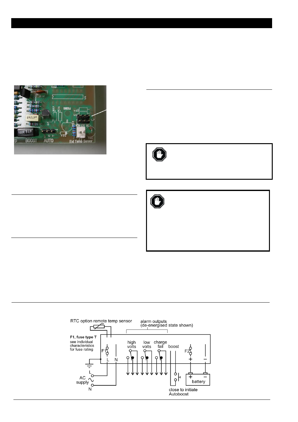
When the circuit board is viewed component side up, with
connectors and fuses uppermost, the 3 pairs of links (ident
label “PL7”) are located at the lower right corner of the
board:
Temperature
Compensation
Links
Guardian is supplied with a link across one vertical pair of
pin-headers (see default settings below). To reconfigure
the temperature compensation, use small, long-nosed
pliers to remove and refit the link:
Link
position
ident
Operation
NON
None. This is the default configuration for
standard Guardians without the RTC option
remote sensor. With this configuration, the
charge output voltage does not vary with
ambient temperature.
Use this option if the batteries are maintained
at a stable temperature around 20°C/68°F.
EXT
External. This is the default configuration for
units supplied with the RTC option remote
temperature sensor.
In this mode, Guardian charge voltage
automatically varies according to ambient
temperature, as measured through the RTC
remote sensor. For each °C increase in
temperature, output voltage automatically
decreases by 3mV per cell, e.g. by 18mV for
a 12V (6 cell) lead acid battery pack.
The RTC sensor should be connected as
close as practicable to the battery being
charged. The sensor is supplied with a 3
Meter lead, wired to the Guardian circuit
board through a pin-header connector (white
connector J2 shown left, located just below
the PL7 configuration links).
Use this option to give an optimum charge
voltage when battery temperature deviates
significantly from 20°C/68°F.
INT
Internal. This configuration gives automatic
charge voltage compensation similar to EXT
above, but with temperature measured by an
on-board sensor (instead of the RTC remote
sensor).
Use this option if the battery temperature is
likely to deviate significantly from 20°C, AND
the charger remains at a similar temperature
to the battery.
WARNING: DO NOT use this option if the
charger (i.e. sensor) and battery ambient
temperatures are significantly different, e.g.
batteries in a cool environment, with charger in
a warmer, enclosed panel. (Note: the charger
itself may cause significant ambient warming.)
AC Input (power supply)
Before AC connection, disconnection or fuse
replacement:
Isolate the AC supply
Ensure a good earth connection to the earth
stud on the charger’s metal chassis.
Ensure the AC supply voltage is compatible
with the charger’s supply rating. Exceeding
the rated voltage may result in damage to
the charger and connected equipment,
and cause serious personal injury.
All Guardian models are fitted with mains AC input fuses,
with ratings as labelled on each charger.
ELECTRICAL CONNECTION (cont.)
Typical Connection
Note: terminal orientation shown for Guardian (open-board); reverse orientation applies for Enclosed Guardian models
Phase-out
/ Discontinued
Product
Check
Availability