Assembling mantel – Desa C36TU User Manual
Page 2
123680-01A
2
www.desatech.com
Header #4
Header
Assembly
Block
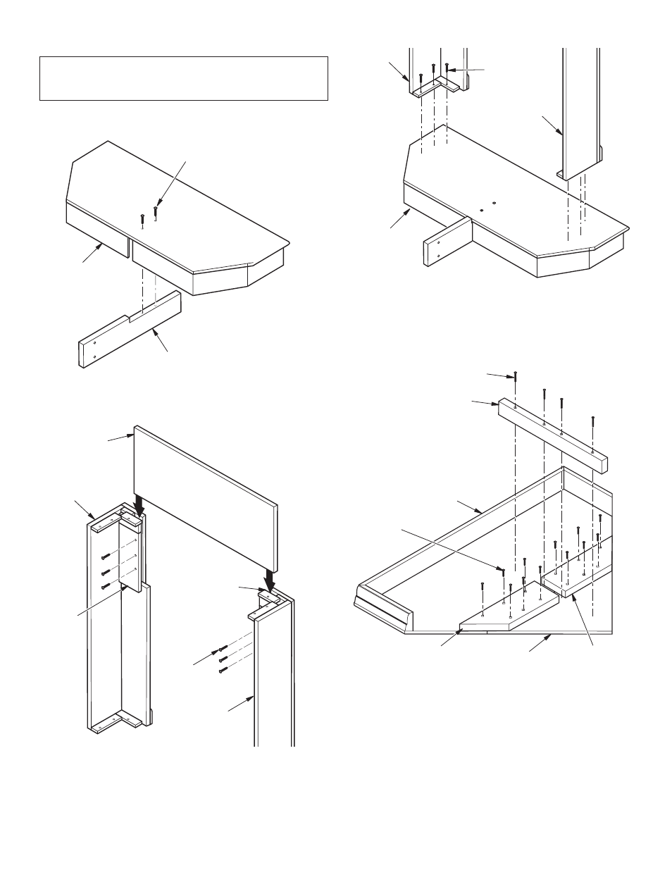
Figure 1 - Installing Base Support
Figure 2 - Installing Header
Base #1
1
1
/
4
" Screws
Base Support #10
1
1
/
4
"
Screws
Left Leg
Assembly #3
Right Leg
Assembly #2
Figure 3 - Installing mantel Base
1
1
/
4
"
Screws
ASSEmbLING mANTEL
Important: more than one person is required to lift
assembled mantel. Lift mantel by leg assemblies. Lifting
by header or mantel top could damage mantel.
Use the following illustrations to assemble mantel. Use only
screws provided.
IMPORTANT: Align mantel left to right on base before install-
ing. Corner of mantel legs must be flush with back of mantel
base before installation (see Figure 4). Use a tape measure
to insure accuracy.
Right Leg
Assembly
#2
Left Leg
Assembly #3
Base #1
Figure 4 - mantel top assembly
Top Center
Support #9
Mantel Top #5
Top Left
Support #8
2" Screws
1
1
/
4
" Screws
Top Triangle #6
Top Right
Support #8
IMPORTANT: Use 2" screws only on top center support. Using
2" screws in any other location will damage mantel.
Header into
Groove on
Legs