AXING BVS 11-03 User Manual
Page 2
Erdung und Montage:
!
Zur Vermeidung gefährlicher Überspannungen (Achtung: Brand-/Lebensgefahr),
müssen die Geräte geerdet werden. Verwenden Sie die am Gerät angebrachte
Erdungsklemme (3).
Verwenden Sie die dem Gerät beiliegenden Montageschrauben und die
Montagelöcher an den Geräten (4).
!
Grounding and Mounting:
! To avoid dangerous power surges (e.g. risk of fire and
) all devices
must be grounded. Use the screw terminal at the device (3).
(4).
danger of life
Use the included mounting screws and the mounting holes of the devices
!
HF-Anschluss:
!
!
!
Schließen Sie den Eingang des Verstärkers am Hausübergabepunkt an.
Verbinden Sie den Ausgang des Verstärkers mit den verwendeten
Antennensteckdosen oder Abzweigern.
Verwenden Sie hierfür ein hochgeschirmtes Koaxialkabel mit einem F-
Anschlussstecker. Passende Kabel und Stecker finden Sie im aktuellen AXING-
Katalog oder unter www.axing.com.
Die Messbuchse am Eingang ist bi-direktional ausgelegt.
RF Installation:
!
Connect the input of the amplifier to the interconnection point. Connect the
output of the amplifier to the antenna sockets or the taps used.
Use a highly shielded coaxial cable with an F connector. Suitable cables and
connectors can be found in the current AXING catalogue or under
www.axing.com.
The test ports at the input is bi-directional.
!
!
3
4
4
Eingang/
Input
Ausgang/
Output
Verwendungsbereich:
Die Geräte sind ausschließlich für den Einsatz zum Verstärken sowie Verteilen
von Radio- und Fernsehsignalen im Haus geeignet! Wird das Gerät für andere
Einsätze verwendet, wird keine Garantie übernommen!
Die Abbildungen zeigen Anwendungsbeispiele für die Verteilung in Sternstruktur
(1) bzw. Baumstruktur (2).
Field of application:
The devices are only suitable for in-house distribution of RF signals! If the device
is used for other purposes, no warranty is given!
The illustrations show application examples of the distribution in star
or tree
structure .
(1)
(2)
Hinweis: Es ist kein Empfang von VHF I im Vorwärtsweg möglich.
Note: VHF I cannot be received in the forward path.
Messbuchsen
Test ports
Downstream
Upstream
1
2
Downstream
Upstream
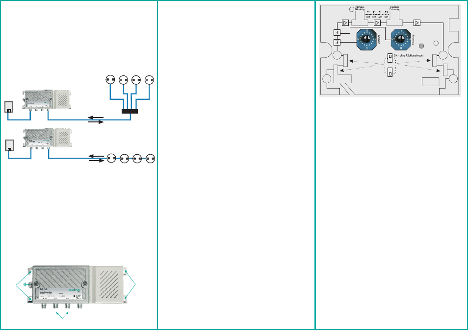
Einstellungen von Dämpfung und Entzerrung :
Betriebsanzeige-LED:
Rückkanalmodule
Mit den diskreten Schaltern (5 und 6) werden Dämpfung und Entzerrung im
Vorwärtsweg (DS) eingestellt.
Mit den Jumpern (7 und 8) werden Interstage-Dämpfung und -Entzerrung im
Vorwärtsweg (DS) eingestellt.
Bevor das Rückkanalmodul eingesetzt wird, müssen die 4 DIP-Switches
(siehe 9 in Zeichnung oben) in die OFF-Position geschaltet werden.
Wird das RK-Modul wieder entfernt, so müssen die 4 DIP-Switches wieder in
die ON-Position geschaltet werden. Nur so ist ein störungsfreier Betrieb
gewährleistet.
Bei Verwendung von Rückkanalmodulen mit 5…65 MHz ist kein
VHF/Band I im Vorwärtsweg möglich.
grün = Betrieb
aus = keine Betriebsspannung
Für die Verstärker steht das Rückkanalmodul (BZU 20-65) zur Verfügung.
Der Verstärker verfügt über eine Betriebsanzeige-LED (POWER):
!
!
!
!
Hinweis:
Adjustments of gain and slope:
Return path modules
For the amplifiers there is the return path module (BZU 20-65) available.
If return path modules with 5...65 MHz are used, VHF/band I in forward
path is not possible.
The amplifier comes with LED (POWER) which shows the operation mode:
Note:
Power indicator LED:
Gain and slope are adjusted with the discrete switches (5 and 6) in the forward
frequency range.
The jumpers (7 and 8) are used to adjust the interstage attenuation and slope in
the forward frequency range.
Before inserting the return channel module, the 4 DIP switches (see 9 in
above drawing) must be set to the OFF.
When the RC module is removed again, the 4 DIP switches must be set to
the ON position again. This is the only way to guarantee troublefree
operation.
green = in operation
out = no power supply
!
!
!
!
Technische Daten:
KBW Klassifizierung
Klasse 3C*
Frequenzbereich
85…1006 MHz
Verstärkung
35 dB
Dämpfung (schaltbar in 1dB Schritten)
15 dB
Leitungsentzerrer (schaltbar in 1dB Schritten)
15 dB
Dämpfung (Interstage)
0/2/4/6 dB
Entzerrung (Interstage)
0/2/4/6 dB
Rückflussdämpfung (mit
18 dB (-1,5 dB/Okt.)
HF-Anschlüsse
F
Messbuchse eingangsseitig, bidirektional
-20dB
Messbuchse ausgangsseitig, unidirektional
-20dB
Maße ca.
192 × 89 × 44 mm
Ausgangspegel
100 dBµV (CSO/CTB )
Rauschmaß.
6,5 dB
RK-Modul)
Schaltnetzteil
80...250 V~/47...63 Hz
Leistungsaufnahme (ohne RK-Modul)
5,5 W
1
£
³
1
CENELEC Raster f=862MHz, 41 ch. 60dB IMA
*mit RK-Modul BZU 20-65
Technical specifications:
KBW classification
Class 3C*
Frequency range
85…1006 MHz
Gain
35 dB
Attenuation (adjustable in 1 dB steps)
15 dB
Slope (adjustable in 1 dB steps)
15 dB
Attenuation (Interstage)
0/2/4/6 dB
Equalization (Interstage)
0/2/4/6 dB
RF Connectors
F
Test port input, bi-directional
-20dB
Test port output, uni-directional
-20dB
Dimensions appr.
192 × 89 × 44 mm
Output level
100 dBµV (CSO/CTB )
Noise figure
6,5 dB
Return loss (with r. p. module)
18 dB (-1,5 dB/Okt.)
Switching mode power supply
80...250 V~/47...63 Hz
Power consumption (w/o r. p. module)
5,5 W
1
1
£
³
*with RP module BZU 20-65
CENELEC Raster f=862MHz, 41 ch. 60dB IMA
OFF = mit Rückkanalmodul
POWER