Panel description, Back panel – Atlona AT PA100 G2 V2 User Manual
Page 4
4
RX
TX
+
-
+
-
+
+
-
-
RS-232
3.5mm
R
MIC
L
IR
1x40Watt@8
2x20Watt@4
48V
MIC
LINE
LOOP
STEREO
BRIDGE
MONO
INPUTS
OUTPUTS
CONTROL
24V
f
INPUT
RX
TX
+
-
+
-
+
+
-
-
RS-232
3.5mm
R
MIC
L
IR
1x40Watt@8
2x20Watt@4
48V
MIC
LINE
LOOP
STEREO
BRIDGE
MONO
INPUTS
OUTPUTS
CONTROL
24V
f
INPUT
atlona.com
Toll free: 1-877-536-3976
Local: 1-408-962-0515
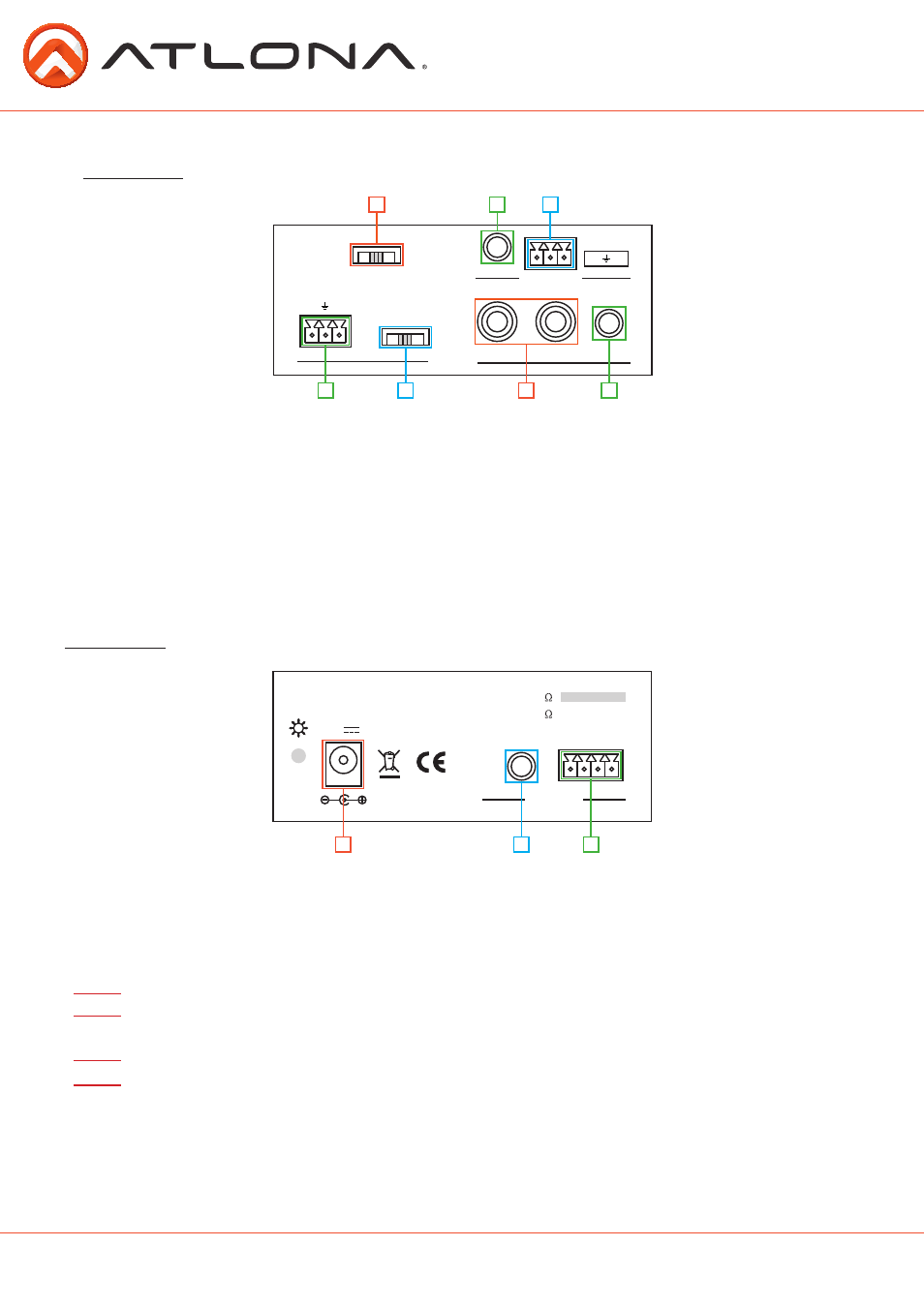
Panel Description
Front Panel
1. Audio output format switch: Use to switch between Stereo, Dual Channel Mono, and
Bridged audio outputs
2. 3.5mm IR: Connect optional IR receiver here for use with optional IR remote (AT-PA1-IR-G2)
3. Captive Screw RS-232: Connect RS-232 here for control
4. Captive Screw Input: Connect a MIC
5. Audio input switch: Switch between 48V Phantom powered condenser MIC, Dynamic MIC, or
LINE input
6. L/R audio: Connect Analog audio into this port
7. 3.5mm audio: Connect Analog audio into this port
1
2
3
4
5
6
7
Back Panel
1. Locking 24V Port: Connect included locking power supply here.
2. 3.5mm variable audio loop out: Loop out to another AT-PA100-G2 or audio amplifier with a
3.5mm stereo audio connector
3. Captive Screw Audio: Connect to speakers
Note:
In a cascading chain, the AT-PA100-G2s will share the source of the 1
st
AT-PA100-G2.
Note:
When using the loop out, the output is variable and dependant on the volume level.
If cascading, the 2
nd
AT-PA100-G2’s volume will change with the 1
st
AT-PA100-G2.
Note:
The volume status is available through RS-232 feedback from the first AT-PA100-G2.
Note:
When cascading, the MIC is only available for the first AT-PA100-G2’s speaker output.
3
2
1