Us and uk face plate change, Panel description, First layer second layer third layer – Atlona AT HDTX WP User Manual
Page 4
4
When switching the product between US and UK face plates, three layers of screws will need to be
removed.
Replace the grey and the white face plates with the correct regional face plate starting at layer 3
until layer one has been replaced.
The first screw that needs removal is the locking screw for the HDMI port.
The top white face plate can be removed once the locking screw has been taken out.
The second set of screws to remove are in the grey tabs attached to the wall plate back box.
Remove all 4.
The back box can be removed now.
The third set of screws for removal are at the bottom of the PCB boards. Place the grey face plate
down and remove the 4 screws from the corner edges. The grey plate is removable now.
US and UK Face Plate Change
First Layer
Second Layer
Third Layer
atlona.com
Toll free: 1-877-536-3976
Local: 1-408-962-0515
DC 24V
-
+
RS232
IR IN
PWR
IR
RX
TX
IR OUT
-
+
HDMI IN
AT-HDTX-WP
PWR
LINK
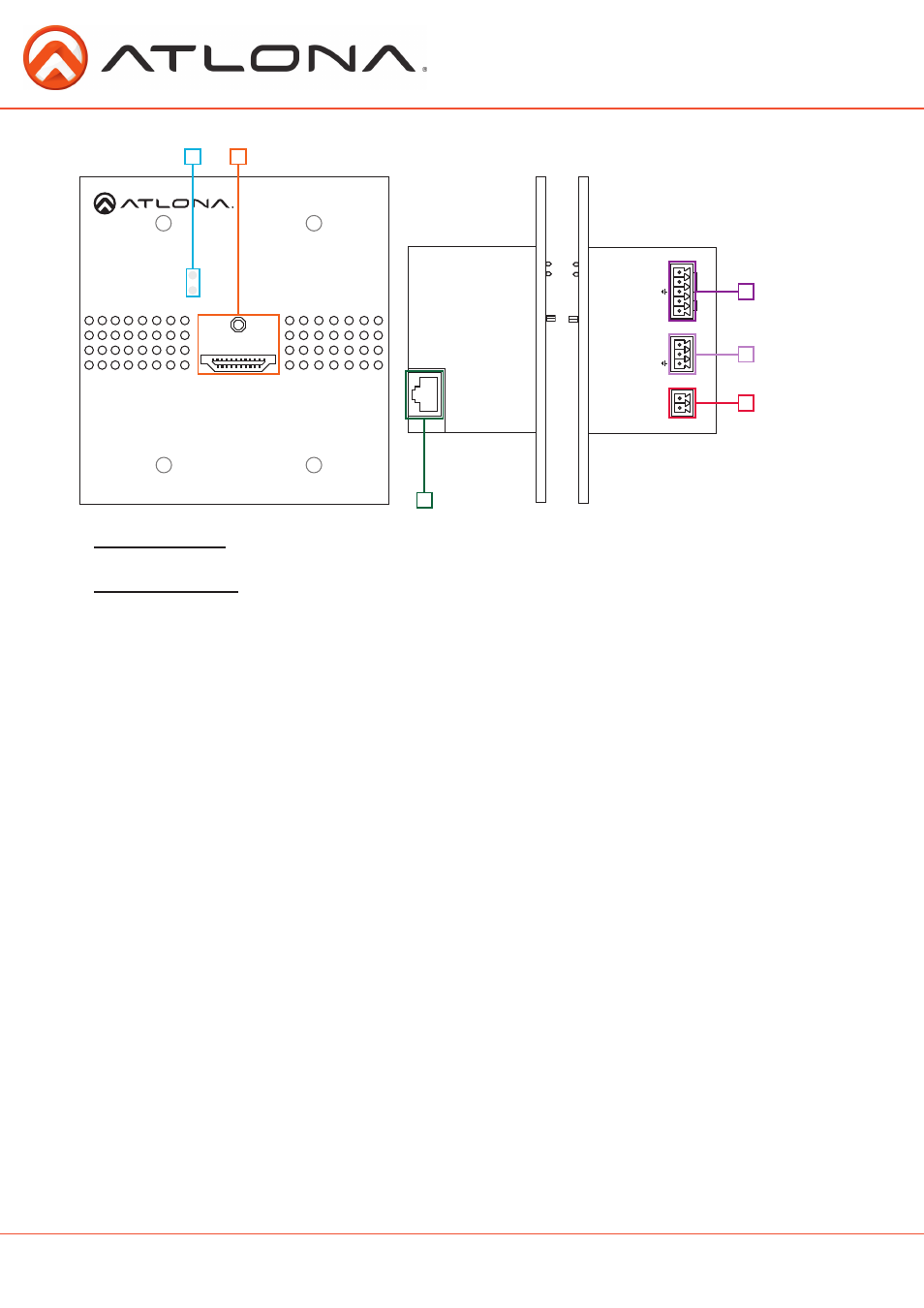
Panel Description
1. Yellow Link LED: Signal Indicator for the CAT5e/6/7 OUT port. LED will remain solid, unless there
is an issue with the cable or signal, then it will blink
Green Power LED: Power indicator. If power is being received steadily the light will remain solid.
If the LED starts blinking power is intermittent or there is a problem with the cable. If LED is
off, no power is passing to the transmitter (check your outlet or the power cable)
2. HDMI IN Port: Connect to HDMI source
3. CAT5e/6/7 IN Port: Connect a category cable from a compatible transmitter to this port
4. a. IR IN Port: Connect the IR receiver to this port
b. IR OUT Port: Connect the IR Emitter to this port
5. RS-232 Port: Bi-directional RS-232, send signal to or from a control system or PC
6. DC 24V Port: Connect the included power cable to this port
NOTE: If receiving power from a compatible HDBaseT receiver or matrix, do not connect the
power supply
2
1
4
6
3
5