Installation – Desa VVDR24 User Manual
Page 10
www.desatech.com
124183-01B
10
Installation and Gas Connection
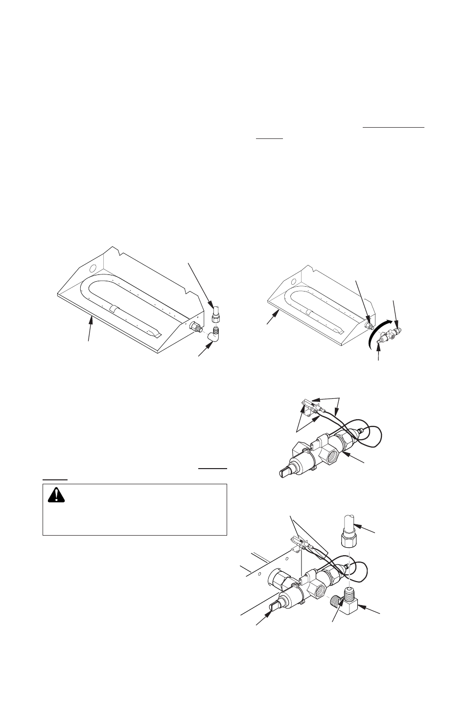
1. Place burner pan assembly in center of
fireplace floor. Make sure front of pan
faces forward.
2. Thread gas supply fitting to fireplace gas
supply pipe. Use thread sealant.
3. Install adapter fitting onto burner inlet fit-
ting using thread sealant on male threads
of burner inlet fitting (see Figure 7). Adjust
to most convenient position.
4. Install gas connector tube to gas supply
fitting. Carefully shape tube to attach to
adapter fitting. Be careful not to cause
kinks in tube.
INSTALLATION
Continued
Figure 7 - Connecting Gas to Appliance
Adapter
Fitting
Gas
Connector
Tube
Burner Pan
Assembly
(Facing Front
of Fireplace)
OPTIONAL GA9050A-1 ON/OFF SAFETY
VALVE/PILOT KIT ASSEMBLY
For additional convenience and safety, or for
propane/LP conversion, an optional ON/OFF
safety valve/pilot kit is available. See Acces-
sories, page 24.
WARNING: You must use a
ON/OFF safety valve/pilot kit for
propane/LP conversion.
Natural Gas Installation
1. Thread gas control valve onto burner inlet
fitting (see Figure 8). Use thread sealant
on male threads of burner inlet fitting. Hold
burner inlet fitting with a wrench to prevent
overtightening connection to the burner.
Make sure control rod is facing the front
(see Figure 8).
2. Attach pilot gas line to pilot outlet of gas
control valve and tighten. Connect ther-
mocouple to rear of gas control valve.
See Figure 9. Do not overtighten. If us-
ing propane/LP gas, see Changing Pilot
Orifice, page 12.
3. Install inlet fitting into inlet opening of gas
control valve (see Figure 10). Use thread
sealant on male pipe threads.
4. Place burner pan assembly in center of
fireplace floor. Make sure front of pan
faces forward.
5. Thread gas supply fitting to fireplace gas
supply pipe. Adjust to most convenient
position.
Burner Inlet
Fitting
Gas Control
Valve
Burner Pan
Assembly
Figure 8 - Installing Gas Control Valve
Control Rod
Figure 9 - Gas Control Valve with
Thermocouple and Pilot
Figure 10 - Installing Inlet Fitting and
Gas Connector Tube
Thermocouple
and Line
Pilot and
Line
Gas Control
Valve
Gas Control
Valve
Gas Inlet
Fitting
Gas
Connector
Tube
Inlet
Opening