Receiver unit: at-hd-v40rs – Atlona AT HD V40SRS User Manual
Page 7
5
Step 3 – Please turn the rotary arrow counterclockwise [ ] from
Mode 0/1
to
Mode 7
. Wait a few
seconds until the LED of the RJ-45 connector dims and then lights again.
Step 4 – Please turn the rotary arrow clockwise [
] from
Mode 7
to
Mode 0/1
. You should have your
desirable audio/video output. If not, please follow the instruction in Note#1.
3. To learn EDID from the HDMI display, please follow the instruction below:
Step 1 –
Please connect the display which you want to read EDID with a HDMI cable to the
transmitter’s HDMI IN and set the rotary arrow at
Mode 7
so the TX can learn the EDID
information from the connected display. The LED on the RJ45 connector of TX will dim and
light again in a few seconds, which indicates the EDID learning procedure is complete.
Step 2 – Please turn the rotary arrow clockwise [
] from
Mode 7
to
Mode 0
or
Mode 1
for desirable
audio setting and enjoy the experience. DO NOT let the rotary arrow pass by
Mode 5
and
Mode 6
which will erase the EDID just learned and restore the default EDID.
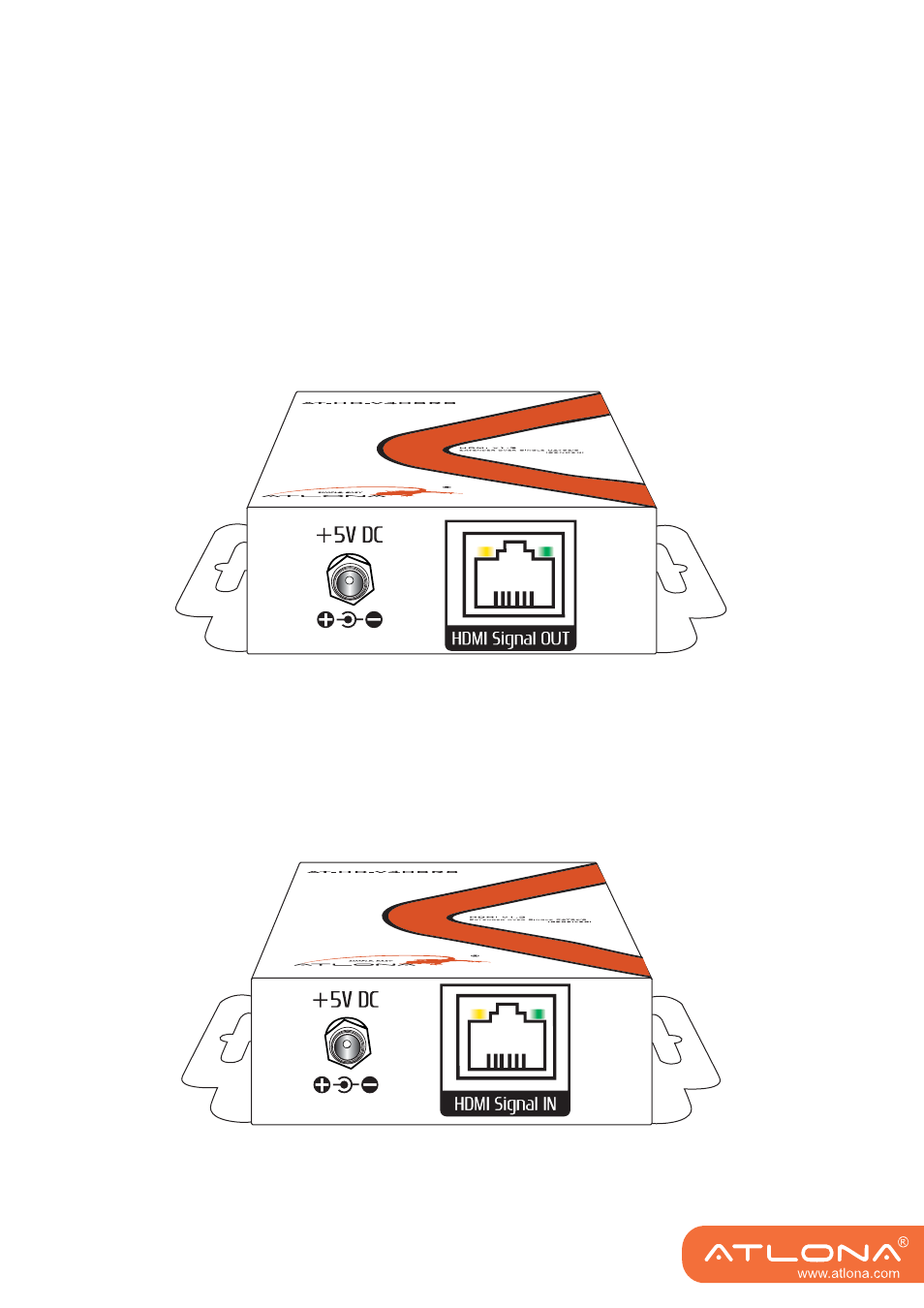
Output Panel
+5V DC: Connect to 5V DC power supply unit.
HDMI Signal OUT: Connect to the HDMI Signal IN on the receiver unit AT-HD-V40RS with a solid Cat-
5/5e/6 UTP/STP cable
Receiver Unit: AT-HD-V40RS
Input Panel
+5V DC: Connect to 5V DC power supply unit.
HDMI Signal IN: Connect to the HDMI Signal OUT on the sender unit AT-HD-V40SS with a solid Cat-
5/5e/6 UTP/STP cable