Ui 5. connections, Installation – ABUS Technologies UI Series of Big Digit Process Indicator User Manual
Page 6
ABUS TECHNOLOGIES INC.
6
UI
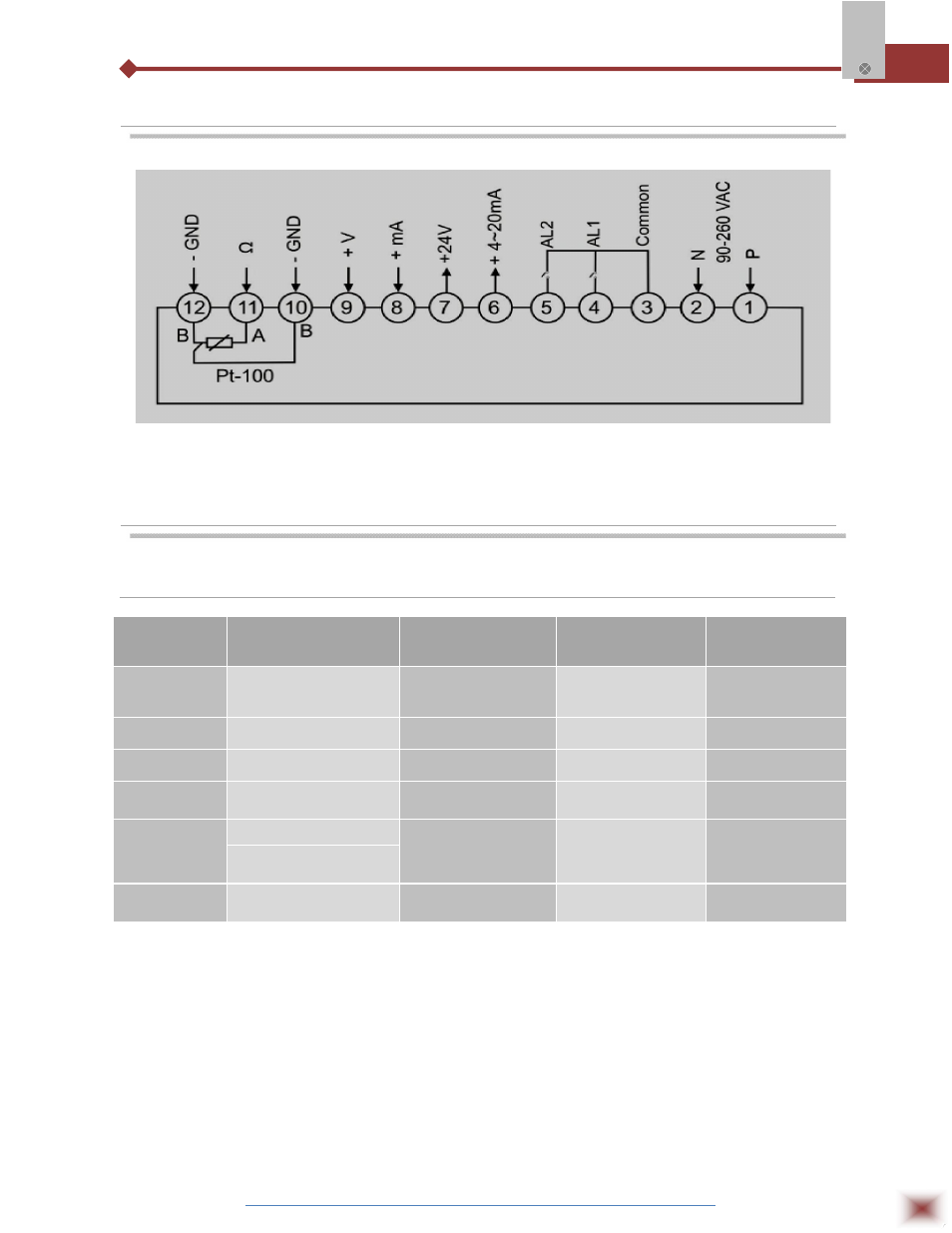
5. CONNECTIONS
Note: For Changes refer to the label on the product
6. INSTALLATION
6.1 Input Signal
INPUT
SIGNAL
MEASURING
RANGE
INPUT
IMPEDANCE
DEFAULT
SETTING
STANDARD
mA
0~1 mA 0~10 mA,
4~20mA
≤ 150 Ω
4~20mA
V(AV/DV)
0~5V, 0~10V, 0~500V
≤ 200 K Ω
DC 0~10V
Pt
-200~650˚C
≤ 0.2 mA
Pt100
mV
0~10 mV, ±100mV
≤ 2 M Ω
0~75mV
Rt
0~400 Ω, 0~10K
≤ 0.2 mA
0~400 Ω
Cu50 Cu100 -50~150˚C
Pr
20 Non-linear Input
1. The factory setting of the input is 4-20mA, 0-10V and Pt. In case of requirement of any
other input signal such as 0-4000hm, Pt100, please contact the manufacturer or your local
ABUS distributors.
2. High Voltage/Current input function needs special order.
3. Analogue output can also be used as Al3, but you can select only one of them, but not
both.
4. Non-Linear input needs special order.