Dakota Digital MCL-3000 User Manual
Page 6
Manual # 650339
Plug in the sealed two pin connector and route the wires over to the bottom right side frame rail. Begin
running the wires back and up behind the transmission and starter area to the battery box, following the
wiring harness that is in place. Use zip-ties to secure the wire harness to the other wires along the
frame.
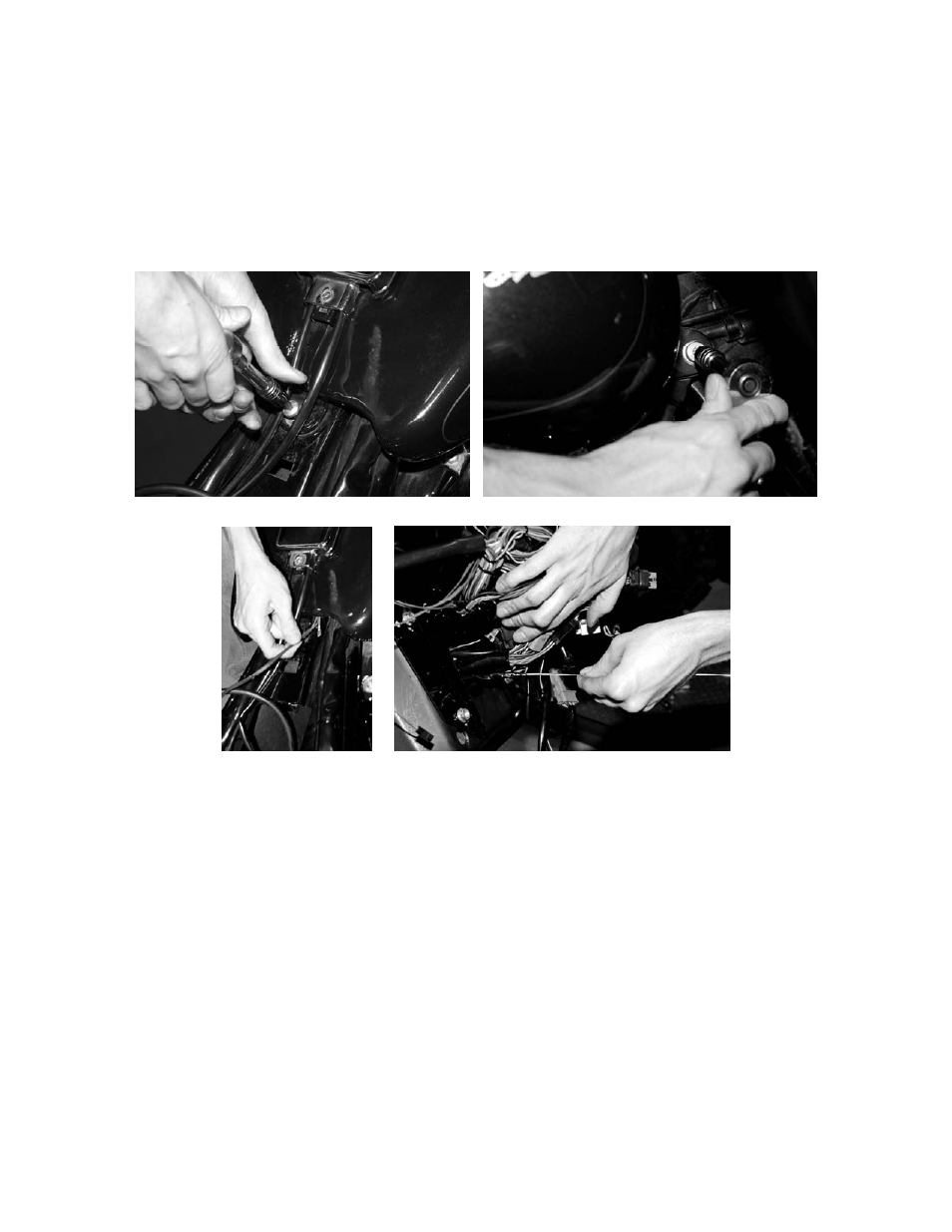
Once you have the wires up through the battery box area it is recommended you remove the tank bolts
to continue running the harness under the tank to its final destination behind the fairing. Use a firm wire
and some electrical tape to fish the wires up the backbone under the tank(filler rod/welding wire works
well for a fish tape). Once clear of the tank, follow the factory wiring harness on the right side and route
wires behind the fairing and over to the oil temp gauge. Make sure to replace and tighten the tank
bolts when done.
Remove rear tank bolt Remove front tank bolts to loosen tank
Route wires under tank Pull the temp sensor wires through the fairing
Now you will have to de-pin a couple wires to connect the temp sensor wires to the factory plug to allow
a factory style plug in connection to the gauge. The pins in the connector have a small locking tab on the
back flat side of the terminal seen in the picture on following page. Use a small allen wrench/pick/or
small screw driver to bend and release this tab. While pushing on the tab, pull the wire gently out from
the back of the connector.
You will need to remove:
BLACK
pin 2 gauge ground(bottom center location in the housing)
BLUE w/ VIOLET pin 3 gauge signal (old air temp sensor, right location, looking at back of housing)
Insert the RED wire from the temp sensor harness into the previous location of the BLUE w/ VIOLET
wire. Insert the other BLACK wire from the sensor harness with a short 3” pigtail into the BLACK wire’s
previous location. Slide supplied piece of heat shrink over the pigtail and connect the spade connector
on the black wire to the original gauge ground wire that was removed from the housing.
This provides
ground for the gauge and sensor. Heat up the heat shrink to protect the ground connection.
NOTE: See Photos on the following page for more details