Channel active antenna combiner, Names and features, Installations – MIPRO ad-808(2ce226)b User Manual
Page 2
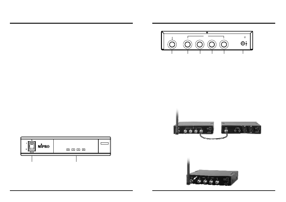
OUTPUT
DCIN(12~15V)
INPUT
C H 4
C H 3
C H 2
C H 1
Thank youfor choosing MIPRO Antenna Combiner System. Beforeoperating,
please read the instructions carefully and completely for optimalperformance.
4-channel Active Antenna Combiner
4-channel Active Antenna Combiner
1.Operatingmanualx1
Main Function:
Main Specifications:
1. Names and Features:
RearPanel
2. Installations:
1.Theinstallationofinput signal
MI-808T
AD-808
2.Antenna Installation
Align thecorresponding coaxialcablestoeachmatingoutputsofeachreceiver.
Foroptimaltransmission,ascertaintheantennasofthecombinerandMI-808T
transmittershavethesamefrequencybands.
(3)
(4)
(4)
(4)
(5)
(4)
FrontPanel
AD-808
(1)
(2)
CH1
CH2
CH3
CH4
ANTENNACOMBINER
AD-808 is a professional UHF 4-channelactiveantennacombiner.The
operating frequency rage is from600MHz to900MHz. Thissystemworks
with MIPRO MI-808T transmitterorsimilarproducts. Uptofourwireless
transmitters can be combinedinto one transmittingantennaformulti-channel
professional applications.
(1)
(2)
Power On/Off Switch:
SignalInputIndicator:
When power-on,thelightilluminates.
When input signal is larger than 66dBM,the
indicator light lits.
The system includes following accessories:
1.Bandwidth:600MHz~900MHz.
2.Channels:Uptofourtransmitters.
3.Indicator: Equips withasignalinputindicator. Inputsignalindicatorislitissignalis
largerthan66dBM.
4.Maximuminput power:+20dBM(100mW).Ideal intermodulationcharacteristic.
Use the coaxialcableswithTNCconnectorstoconnecttheoutputsof MI-808
to the inputsofAD-808andthenfasten.
Ascertain length of the coaxial cables is asshort aspossibletoobtainthe
optimal reception. This systemconnectsuptofourMI-808Ttransmitters.
(3)
(4)
(5)
Antenna output Jack:
Signal input Jack:
DC Power Input Jack:
To connectthecombinedsignal andoutputtoAntenna
Toconnecttheoutputoffourtransmitters.
To connect 12~15DCfromtheAC/DC adapter.