Act multi channel wireless receiver – MIPRO act-707f User Manual
Page 4
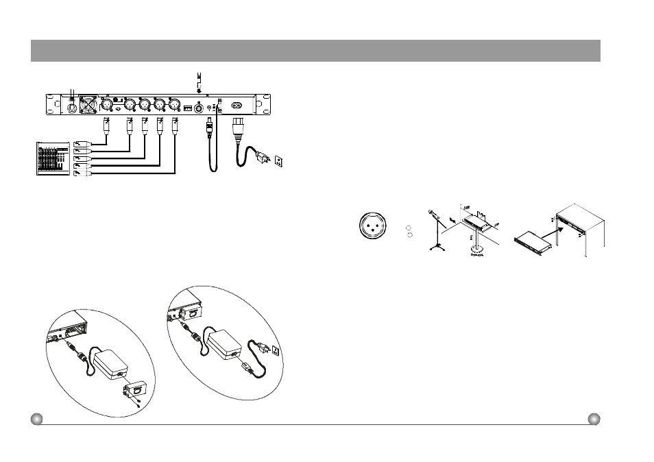
1.
Install 2 separate antennas on theantennasockets(11), ( 20) on therear panel.
Illustrated in figure3.
2.
Connectingthepowersupply:Whenusing AC power supply, attach the female end
o f t h e power cord to the receiver (22) and plug themale end to theAC power
outlet. Afterward, take the DC output cord from thepower module and pluginto
theDCinputsocket(21). Illustratedin figure 3.
3.
ACT-707 adapts switching power supply m odule. The switching power supplynot
only can be used whileconnected externally (figure 4), but also stock internally in
thestoragecase on the back o f thereceiver (figure 3).
4.
Audio OutputConnection
6.
To ensurebestreceptionpossible, receiver must be installed at least onemeter
above ground. In addition, the distance between transmitter and receiver must b e
more than one meter a n d a w a y f r o m n o i s e . (Shows in figure 6)
7.
On the frontpanelofthereceiver,4openings arepre-drilled for instant installation
on the standard19-inchrackcase. (Shows infigure7)
4
5
3:COLD -
+
1:GND
2:HOT
3
2
1
External P o w e r Supply Unit
MixedOutput: Balancedoutput socket (XLR) must connect to thebalanced input socketofthe
mixer. This output socket generates themixedoutput of C h . 1 ~ C h . 4 a n d t h e o u t p u t
sensitivity can be adjusted toAUX level or MIC level by the level switchon the right side of
thesocket. Generallyspeaking,AUXlevelistocoordinatetheinputsensitivityofelectricguitar
amplifier.
IndependentOutputs:Thereare fourbalanced output sockets forindividual outputs of
CH1~CH4. Allusebalanced(XLR) output sockets and theoutput sensitivities h a d b e e n p r e -
set t o m i c l e v e l t o coordinate the i n p u t level of t h e m i x e r (MIC level aswell). (Figure 5
5.
Antenna Socket: Theantenna socketprovides 8 Volt DC power, whichenable you
to p a i r with MIPRO'santennaboosterdirectly. When the connecting cable for the
antenna is more than 10 meter, it is recommended toinstall antenna booster to
make up thesignal loss caused by the cable a n d t o e n s u r e t h e sensitivity of
reception.
InternalPowerSupplyAssembly
ACT MULTI CHANNEL WIRELESS RECEIVER
3. INSTALLATION O F THE RECEIVER
(Fig.3)
(Fig.5)
(Fig.6)
(Fig.7)
(Fig.4)
ACT MULTI CHANNEL WIRELESS RECEIVER
C H 3
AFOUTPUT
MIXED
LEVEL
MIC
AUX
2:HOT
3 . C O L D
1:GND
C H 4
C H 2
C H 1
+8VDCOUT
ANTENNAB
REMOTE
DCIN(12~15V)