Placement of the ipd-4500 system, Ipod®/iphone® connection, Power supply – Lenco IPD-4500 User Manual
Page 3
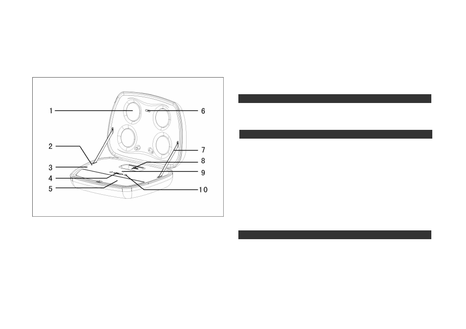
IPD-4500 Diagram:
1. Speaker unit
2. External power supply jack
3. Audio source input jack
4. Power switch
5. Battery/headphone/remote control storage compartment
6. Remote control signal receiving window
7. Hinge
8.
iPod®/iPhone®
30PIN socket
9. Battery indicator light
10. Sound volume control button
Placement of the IPD-4500 system
It is best to place the IPD-4500 system on a horizontal flat surface close to you (1-2.5 meters). The IPD-
4500 system can be placed near video display equipment such as a television and computer monitor
without resulting in graphic distortion.
iPod®/iPhone® connection
Warning: Ensure that the IPD-4500 system is in the POWER OFF mode before making any connections and
before docking the
iPod®/iPhone®
into the IPD-4500 system. In order to guarantee that the system works
properly on first use, please carefully follow the connection sequence as described below and in the order
indicated.
An
iPod®/iPhone®
model with a 30PIN connector can be directly inserted into the special socket in the
IPD-4500 system, while for an
iPod®/iPhone®
model without a 30PIN connector or any other kind of
player, a 3.5 mm stereo cable is used to connect with the AUDIO IN port on the operating panel of the
IPD-4500 system, thus accomplishing a signal input connection between the player and the IPD-4500
system.
The IPD-4500 system can be used when either of these connections is completed and it has been
confirmed that the built-in rechargeable batteries have sufficient power or there is an external power
supply.
Power supply
Power for the IPD-4500 system can be supplied from the built-in rechargeable batteries provided inside
the main unit or from an external AC power source through an external 9 V DC@ 2A power supply adapter.