Lenco CS-341 User Manual
Page 6
INSTALLING PROCESS
WIRING DIAGRAM
1. This player can only be used by the 12V DC cathode grounding electrical system.
2. Don’t connect the terminals of the car battery until the player is absolutely with well erection joint.
3. Please make sure to connect the yellow wire to the positive of the battery(+).
4. When change the fuse. Please make sure the specifications are same.
5. Using good quality speaker with 4-8 ohm can result in the best effect of the equipment.
2
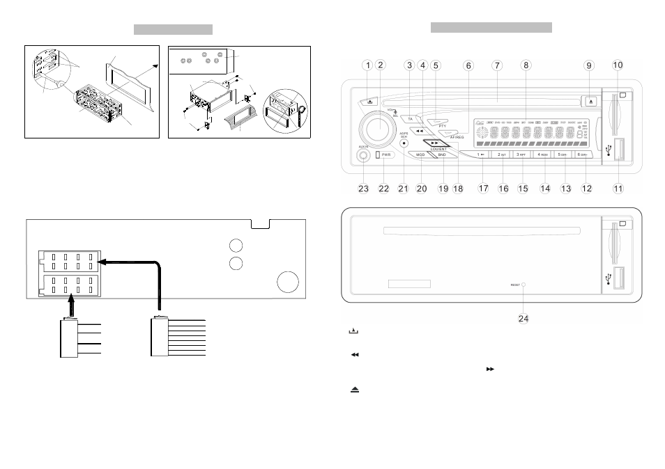
CONTROL PANEL AND FUNCTIONS
CONTROL PANEL AND FUNCTIONS
1.
button.
13. “5/ DIR-” button.
2
.
“VOL/SEL
”
button.
14 “4/ RDM” button.
3. “TA” button.
15. “3/ RPT” button.
4. “
” button.
16. “2/ INT” button.
5. “PTY” button.
17. “1/ >II” button
6. “AF/REG” button. 18. “
” button
7. DISC
slot.
19. “BND / LOU /ENT ” button.
8.
LCD display
20. “MODE” button.
9.. “
” button. 21. “AS / PS / SCH /” button.
10. SD SARD
slot.
22. “POWER” button.
11. . USB
port.
23.
“AUX IN” jack.
12
“6/ DIR+” button.
24. .
“RESET” button.
3
Sleeve
Dashboard
Tabs
Screwdriver
and bond the tabs if
necessary.
2. Put the sleeve
to the dashboard.
Dashboard or Console
Hook
Screw
Mounting Bracket
Factory Radio
T, N
Screw Holes marked
Side View showing
Screw
method.
can using this mounting
Nissan, Toyota's vehicle
(RED)
(WHITE)
LINEOUT-Lch
LINEOUT-Rch
AM/FM ANTENNA
P
A
R
T
A
BLACK
RED
BLUE
YELLOW
B+
AUTO ANT
GROUND
ACC
FRONT R-ch-
FRONT R-ch+
REAR R-ch-
REAR R-ch+
FRONT L-ch-
FRONT L-ch+
REAR L-ch-
REAR L-ch+
GREY/BLK
GREY
PURPLE/BLK
PURPLE
GREEN/BLK
GREEN
WHITE
IS
O
P
A
R
T
B
IS
O
WHITE/BLK