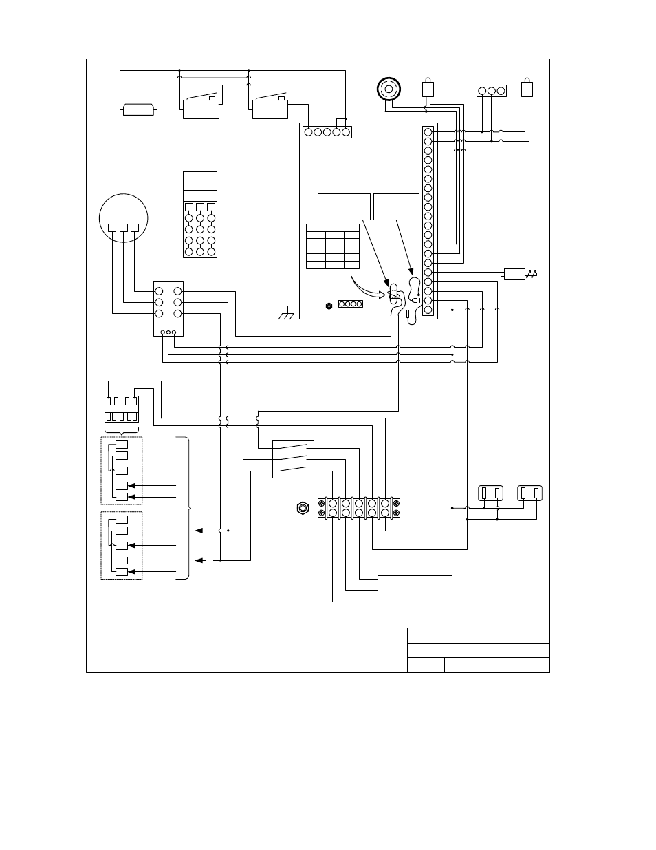
230 v, 208 v – DoorKing 9310 User Manual
Page 54
Title:
Date:
Rev.
Dwg. No.
DOORKING, INC., INGLEWOOD, CA 90301
1
2
3
4
5
N.O.
N.C.
COM
N.O.
N.C.
COM
Wh
it
e
Re
d
Y
e
llo
w
Bl
u
e
Limit
Limit
Partial Limit
P2
P1
1
2
3
4
5
6
7
8
9
10
11
12
13
14
15
16
17
18
19
20
4403-010
Circuit Board
Solenoid
Alarm
White
Red
Yellow
Black
P3
Current Sensor Donut
Motor Volt-Ph Turns
½ HP
All
2
1 HP
Sgl Ph
1
1 HP
208 - 3
5
1 HP
230 - 3
5
115 VAC
Convenience Outlets
White
Black
White
Black
Green
White
208/230 V
Three Phase
Input
Black
Black
Black
Black
Red
Blue
Operator Power
Route black motor
wire (see table)
directly through
current sensor donut.
Connect red
sensor wire
directly to lug
opposite term 19.
230 V
L2
L1
5
4
3
2
1
5
4
3
2
1
208 V
L1
L2
5 4
3
2 1
Blue
Red
Black
White
Black
L2
L1
Blue
White
Red
Blue
Red
Black
L3
L2
L1
Motor 1 HP
Blue
Red
Black
L1
L2
L3
1
2
3
7
8
9
4
5
6
P4
P5
P6
208/230
Motor
Wiring
C
4403-1-202346-3
8/08
Model 9310 Wire Diagram
1 HP 208/230 VAC Three-Phase
Solid State
Motor Relay
115 VAC
Output
Input
Chassis
Alarm Reset
1
2
3
Rec’vr Term
White
Brown
Orange
Start But
Page 54
9310-065-H-8-08