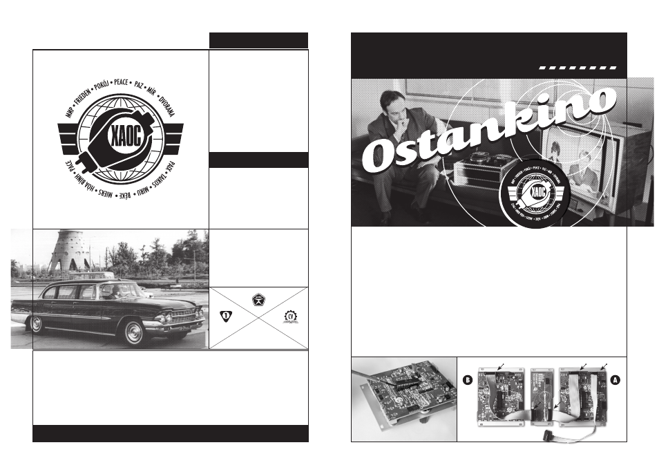
Caution, Working cl ass electronics – Xaoc Devices Ostankino User Manual
Page 2
PRODUCT FEATURES
TECHNICAL DETAILS
• voltage and manual control over
2 Moskwa sequencer units
• synced dual 8-step patterns or
merged 16-step sequences
• individual clock outputs for each
sequencer unit
• individual gate/trigger outputs for
every step on each sequencer unit
• voltage controlled step dialing
• summed CV and gate outputs
• eurorack standard synthesizer
module, fully Doepfer compatible
• 1o hp wide
• requires 2 Moskwa modules
• no direct power connection needed
APPROVED
BY THE PEOPLE’S COunCiL
FOR MUTUAL ECONOMIC AID
WARRANTY INFORMATION•XAOC DEViCES WARRAnTS THiS PRODuCT TO BE FREE FROM AnY COnSTRuCTiOn DEFECTS FOR OnE
YEAR FROM THE DATE OF PuRCHASE. DuRinG THAT PERiOD AnY MALFunCTiOninG uniTS WiLL BE REPAiRED, SERViCED AnD CALiBRATED
WiTH CuSTOMER COVERinG THE APPROPRiATE TRAnSiT FEES•WARRAnTY DOES nOT COVER AnY PROBLEMS RESuLTinG FROM THE inCOR-
RECT inSTALLATiOn OR VOLTAGE SuPPLiED, ABuSiVE TREATMEnT OR AnY OTHER OBViOuS uSER-inFLiCTED FAuLT•WE ARE STiLL HAPPY TO
HELP AFTER THE WARRAnTY PERiOD, HOWEVER WE RESERVE THE RiGHT TO CHARGE FOR LABOR, REPLACEMEnT PARTS AnD TRAnSiT•in
CASE OF AnY PROBLEM PLEASE COnTACT uS iMMEDiATELY: [email protected]•
XAOC SALUTES•MuFF WiGGLERS, OuR AWE-
SOME DiSTRiBuTORS, nORDVARGR, WOuTER JASPERS, SERGEi HAnOLAinEn, MODuLARnE.inFO & COMRADES WORLDWiDE•ALL RiGHTS
RESERVED © 2013 XAOC DEViCES•MAnuFACTuRER RESERVES THE RiGHT TO CHAnGE SPECiFiCATiOnS AT AnY TiME•MADE in EuROPE
VISIT
XAOCDEVICES.COM FOR uPDATES, MAnuALS, TuTORiALS AnD PARAPHREnALiA
WORKING CL
ASS
ELECTRONICS
SEQUENCE C
OMMANDER
EXPANSION MODULE
MODEL OF 1
966
CHIP REPLACEMENT
Ostankino requires Moskwa
microcontroller ICs to be
replaced. The new firmware
revision that takes advantage
of the expander functionality,
improves the performance and
adds some new features.
Turn your system off, then
unscrew and unplug the mod-
ules. Put them on the table,
knobs down. Now, remove
the old chip. Pry it up gently
using a toothpick or tweezers,
as shown on [Fig.1]. Then, put
the new chip in place. Observe
the orientation carefully, the
notch points down! Then, gen-
tly, push the chip until it sits
safely in the socket. Repeat the
operation for the remaining
Moskwa unit.
CONNECTING THE CABLES
Looking at the back side of
modules, attach the 16-pin
inter-connectors as shown on
[Fig.2]. The red stripe points
to the right on the Moskwa
(
expander
header, remove
the jumper first), and points
up on the Ostankino (a and b
header, should arrive attached
already).
Clear 50hp in your cabinet and
place the modules in it. Only
Moskwa A requires a power
cable now (you can simply
remove a power cable from sec-
ond unit). The expander module
and second Moskwa will draw
their power from the first unit.
Finally, check if the orientation
of the power cable is correct,
and thats it, you’re good to go!
BEFORE ATTEMPTinG TO SWAP THE CHiPS OR COnnECTinG YOuR SEquEnCER MODuLES
TO THE EXPAnDER, PLEASE READ THE FOLLOWinG inSTRuCTiOnS CAREFuLLY! WROnG
CABLE OR CHiP ORiEnTATiOn WiLL inEViTABLY DAMAGE THE MODuLES! THiS iS DAMAGE
WHiCH iS nOT COVERED BY WARRAnTY SO PLEASE uSE DuE CAuTiOn WHEn inSTALLinG!
CAUTION!
[Fig.2] INTER-CONNECTORS ORIENTATION
[Fig.1] REPLACING THE CHIP
stripe