Ignition/boost control installation – Vortech 1987-1997 Ford 7.5L Truck/SUV User Manual
Page 16
P/N: 4FB020-010
©2001 Vortech Engineering, LLC
All Rights Reserved, Intl. Copr. Secured
27JUL01 V1.1
(7.5 Ford 460(4FB V1.1))
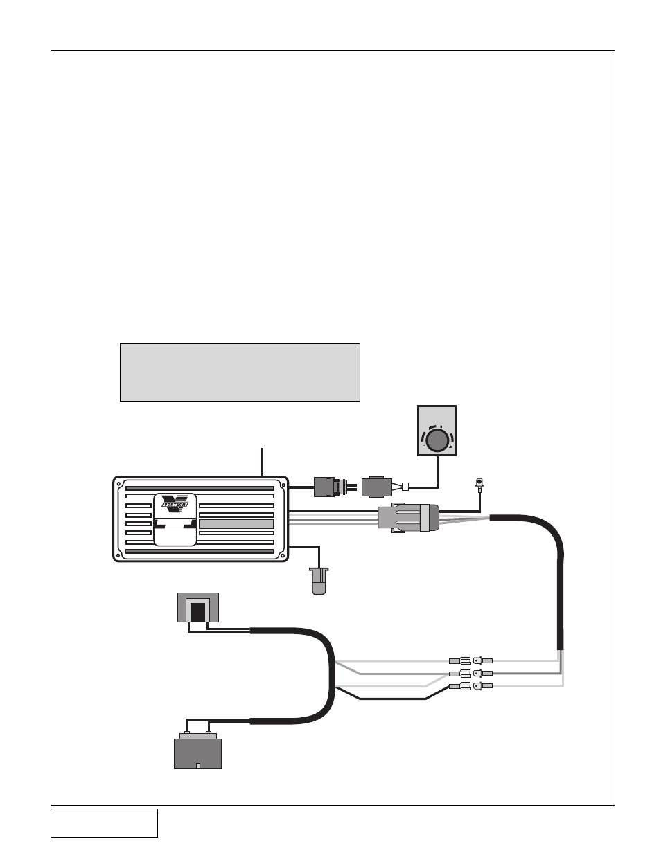
A. The Ignition/Boost Control unit has been prewired
for installation convenience. Installation is a
simple matter of disconnecting the stock con-
nector at the ignition coil and plugging in the new
adapter. Then plug the stock connector into the
adapter. (See
Fig. 12-a.)
B. The next step is to provide a good ground for the
black wire and mounting the box in as cool a
place as possible under the hood. The box
should be mounted with the aluminum cover on
the bottom.
C. Connect the vent to manifold pressure by splic-
ing into the FMU manifold pressure line with the
supplied 5/32" hose and TEE.
D. Route the Ignition/Boost Control wires through
the firewall from the interior side. Mount the
knob in an easily accessible place.
E. Connect the wires to the plastic oval wiring
connector on the Ignition/Boost Control unit
using the snap-on connector supplied in the
Ignition/Boost Control kit.
NOTE: The wiring to the Boost/Control knob
can be matched to either of the corre-
sponding wires in the boost retard
connector.
8
12.
IGNITION/BOOST CONTROL INSTALLATION
Fig. 12-a
BOOST
RETARD
0
1
2
3
SUPERCHARGERS
Ignition/Boost
Control
MANUFACTURED FOR
VORTECH SUPERCHARGERS
BY
MSD
®
BLACK
WHITE
RED
ORANGE
BLACK
WHITE
RED
ORANGE
IGNITION
COIL
FROM FACTORY COIL HARNESS
MAGNETIC PICKUP
CONNECTOR (NOT USED)
BOOST
RETARD
CONNECTOR
GROUND
TO MANIFOLD
VACUUM