Vortech 1987-1996 Ford 5.0L/5.8L Truck/SUV User Manual
Page 19
P/N: 4FC020-010
©2000 Vortech Engineering, Inc.
All Rights Reserved, Intl. Copr. Secured
13SEP00 V1.3
(86-93 5.0 Lt Truck(4FC))
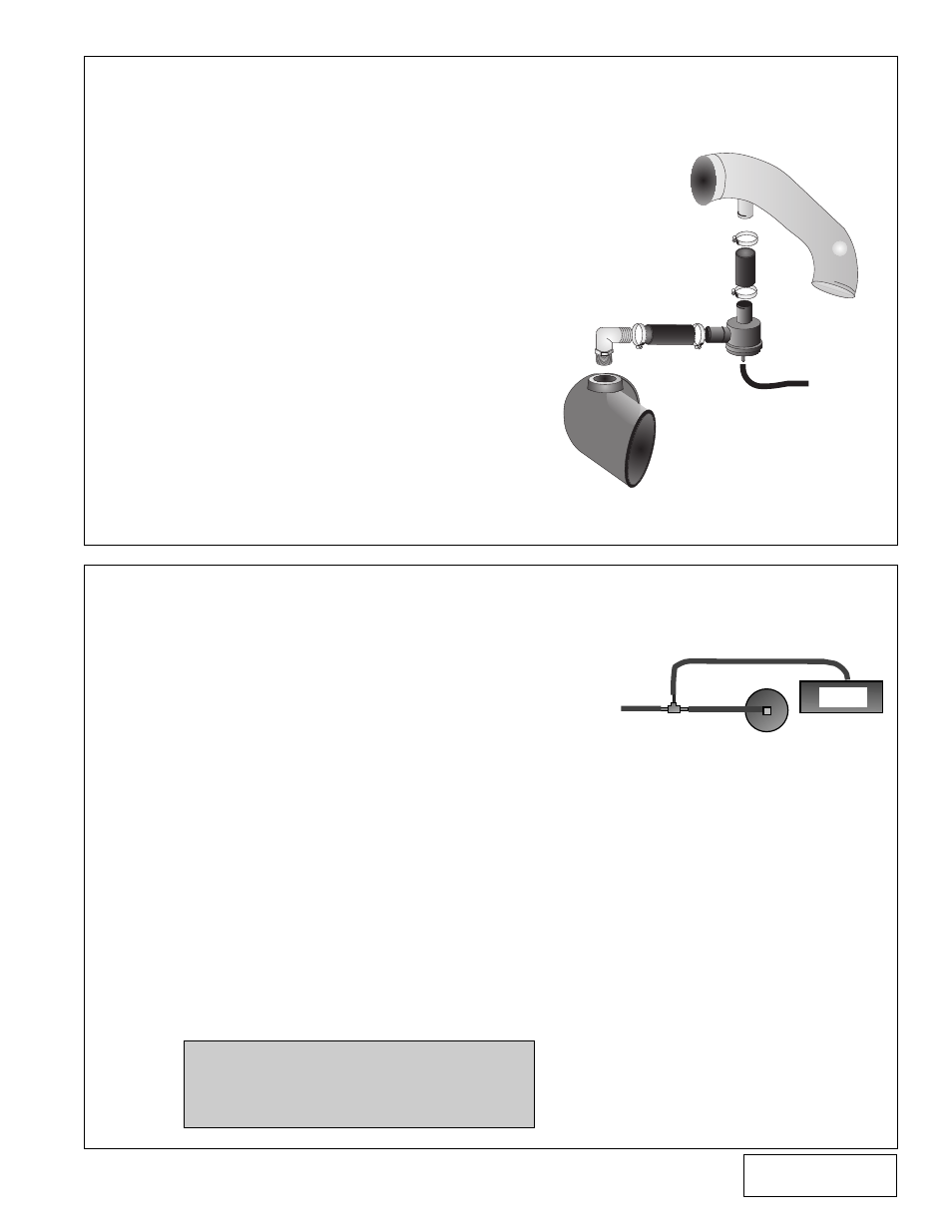
13. 5.8 LIGHTNING SUPPLEMENTAL INSTALLATION INSTRUCTIONS
FOR THE BYPASS VALVE
14.1 IGNITION/BOOST CONTROL UNIT INSTALLATION
(NON-LIGHTNING TRUCKS ONLY)
A. The Ignition/Boost Control unit has been
prewired for installation convenience. Instal-
lation is a simple matter of disconnecting the
stock connector at the ignition coil and plug-
ging in the new adapter. Then plug the stock
connector into the adapter.
B. The next step is to provide a good ground for
the black wire and mounting the box in as
cool a place as possible under the hood. The
box should be mounted with the aluminum
cover on the bottom.
C. Splice the supplied 5/32" hose and TEE into
the FMU vacuum line and connect to the
Ignition/Boost Control Unit (see
Figure 14-a
).
D. Route the Ignition/Boost Control wires
through the firewall from the interior side.
Mount the knob in an easily accessible place.
E. Connect the wires to the plastic oval wiring
connector on the Ignition/Boost Control unit
using the snap-on connector supplied in the
Ignition/Boost Control kit.
A. Screw the fitting into the new inlet elbow as
shown in the graphic.
B. Install the inlet elbow onto the supercharger
with the fitting on top and pointing towards
the small tube branched off of the discharge
tube.
C. Place the hoses, as shown, on the valve and
secure with the clamps provided.
D. Install the valve with the hoses connected,
between the inlet elbow and discharge tube.
Secure hoses with the clamps.
E. Attach one end of the small sensor hose
onto the valve.
F. Connect the 5/32" vacuum hose from the
bypass valve to the intake manifold vacuum
fitting. See
Figure 11-b
on page 7.
G. Make sure everything is secure and that no
fuel lines or wires have been accidentally
moved into harm's way.
MSD
FMU
MANIFOLD
VACUUM
NOTE: The wiring to the Boost/Control
knob can be matched to either
of the corresponding wires in
the boost retard connector.
9
Figure: 13-a
Figure: 14-a
INLET ELBOW
CONNECT TO MANIFOLD PRESSURE
BYPASS VALVE
DISCHARGE TUBE