Tiptop Z5000 Multi-Effect User Manual
The basics: connecting the module, Figure a figure c figure d, Figure b figure e
IN
MIX
DRY
WET
MIN
MAX
MIN
MAX
MIN
MAX
MIN
MAX
OUT
CTRL
LEFT IN
CV IN
VC-PARAMETER
CV
1 Hall Reverb A
2 Hall Reverb B
3 Hall Reverb C
4 Room Reverb A
5 Room Reverb B
6 Room Reverb C
7 Plate Reverb A
8 Plate Reverb B
9 Plate Reverb C
10 Nonlinear Rvrb
11 Chorus
12 Flanger
13 Delay
14 Chorus/Room
15 Chorus/Delay
16 RotarySpeaker
(MONO)
+
-24db
-12db
-6db
0db
RIGHT IN
LEFT OUT
(MONO)
RIGHT OUT
2
3
5
4
8
7
6
1
15
14
12
13
9
10
11
16
L
R
Input
Z5000
INPUT
OUTPUT
24Bit 48Khz
PROGRAM
VC-Stereo Multi Effect Processor
V C D S P
+
+
+
+
TM
Z5000 Voltage Controlled Digital Signal Processor
Quick Start Guide
The Basics:
Connecting The Module:
Width- 14HP
Power Requirements- +/-12V or +/-15V
Current Draw- 160mA
Maximum Audio Input- 16Vpp (Before Clipping)
Maximum Audio Output (Dry)- To Rail
Maximum Audio Output (Wet)- 16Vpp
CV Input Range- 0 to +5V
Hall Reverb A
Hall Reverb B
Hall Reverb C
Room Reverb A
Room Reverb B
Room Reverb C
Plate Reverb A
Plate Reverb B
Plate Reverb C
Non-linear Reverb
Chorus
Flanger
Delay
Chorus/Room Reverb
Chorus/Delay
Rotary Speaker
Effect
Effect Parameter
Reverb Decay Time
Reverb Decay Time
Reverb Decay Time
Reverb Decay Time
Reverb Decay Time
Reverb Decay Time
Reverb Decay Time
Reverb Decay Time
Reverb Decay Time
Reverb Decay Time
Chorus Depth
Flanger Rate
Delay Time
Reverb Decay Time
Delay Time
Speed Low/High
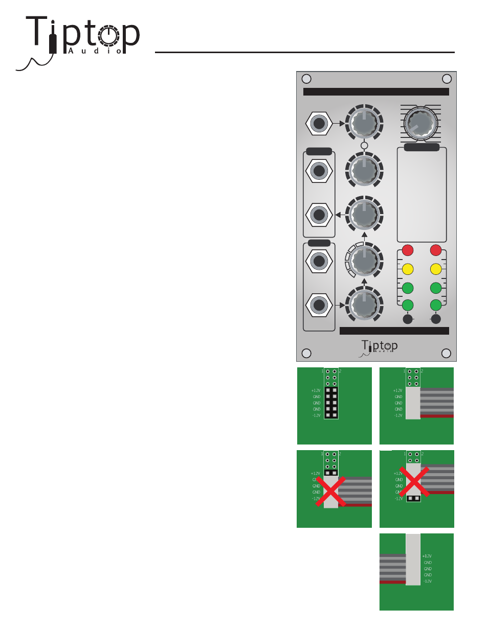
Figure A
Figure C
Figure D
TM
Figure B
Figure E
Find the power connection header on the PCB perpendicular to the
front panel. It is located toward the top of the module and should
look like Figure A. Orient the ribbon cable so that the red line is on the bottom and oriented
with the -12V label on the connection header as in Figure B. Ensure that the connector fully
covers the header (as in Figure B) and press firmly to ensure a proper mechanical
connection. Additionally, please ensure that the connector is properly oriented on the
power connection header before powering the module (Figures C and D). Once connected
to the module, ensure that the ribbon cable connects with the red line on the bottom and to
the matching -12V on the power supply bus, as in Figure E.
Warning: Improper connection
of the power supply can permantently damage the module.
Important Note:
All of the effects listed above can be fully controlled using a
continous CV signal with the exception of Room Reverb B, Non-linear
Reverb, and Delay. Though not originally designed to be controlled
using a CV signal, it is still possible to use a CV input or the
CTRL knob to adjust a parameter on each of these effects.
However, these three effects will generate digital artifacts known
as “zippering” when adjusting a parameter using the CTRL knob
or with an external CV signal. Some users may find this zippering
effect useful sonically and this was the primary motivation behind
leaving these effects available in the module. Users who wish to
have CV control over this effect are encouraged to experiment
with a stepped CV signal from modules such as a Sample and
Hold or Sequencer. This should provide a certain degree of
control over the effect parameter with a limited amount of
“zippering”.