Rear panel layout – Simaudio 860A Amplifier User Manual
Page 8
860A Dual-Mono Power Amplifier
____________________________________________________________________________________
8
Rear Panel Layout
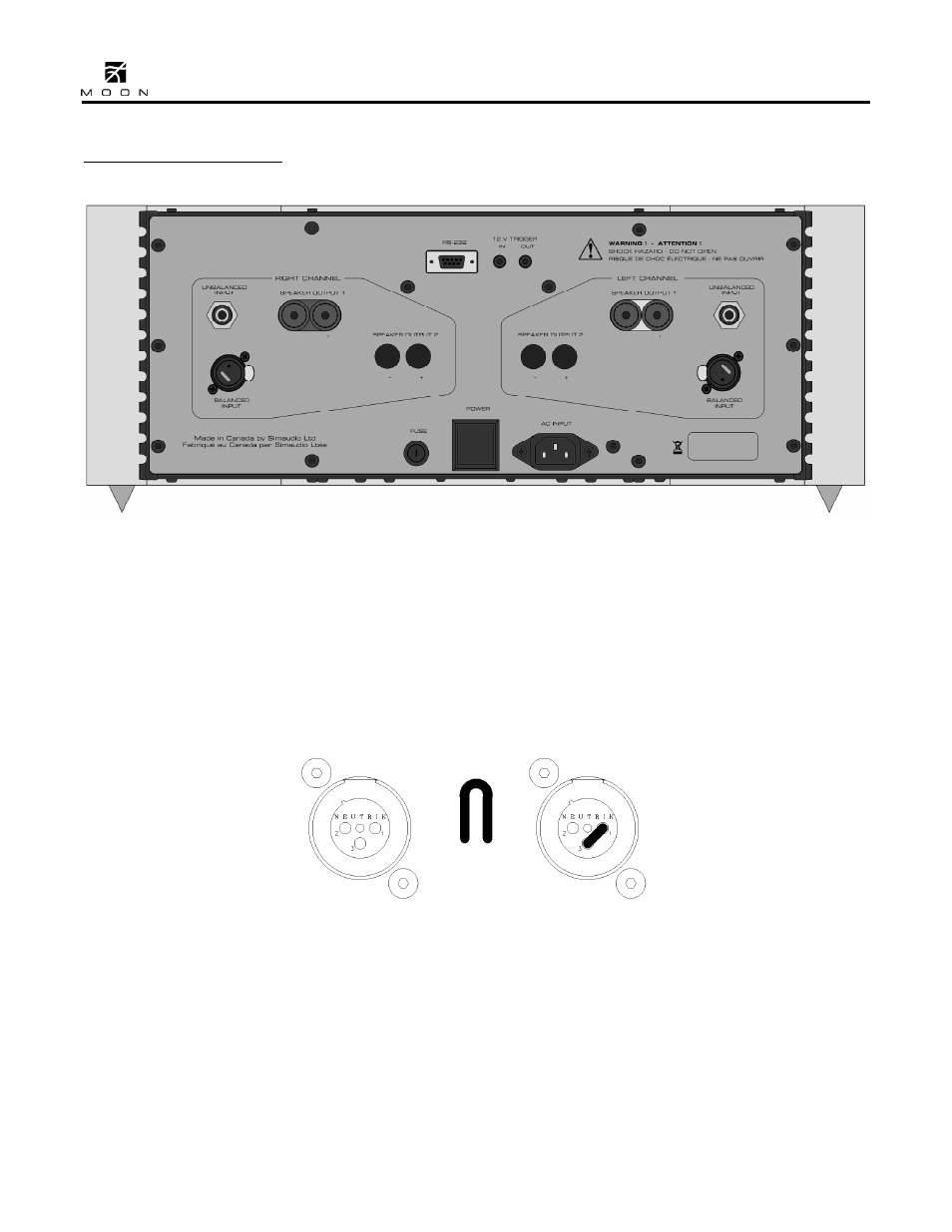
Figure 1: Rear panel of Moon 860A Dual-Mono Amplifier
The rear panel will look similar to Figure 1 (above).
Each channel has one balanced (differential) input
on an XLR connector and one unbalanced (single-
ended) input on a RCA connector. There is no
switch to toggle from balanced mode to single-
ended mode. You may operate the amplifier in
either mode, but only one mode at one time for
each channel. When you’re using the balanced XLR
inputs, you must first remove the factory
installed “dummy” XLR jumpers (see figure 2
below) from the back panel XLR connectors and
store them in a safe place. These jumpers are
required ONLY when using the single-ended RCA
inputs. If you decide to switch to single-ended input
mode, you must reinstall the XLR jumpers (between
pins 1 and 3) exactly as show below:
Figure 2: XLR connector without and with jumper accessory
There are two pairs of heavy duty gold-plated
speaker binding posts for each channel labelled
“Speaker Output 1”.
The upper mid-section has an RS-232 input on a
DB9 connector. To the right of this connector are
two 12 Volt triggers, each on a 1/8” mini-jack; one
input and one output, the latter for use in the event
that wish you to “daisy chain” a second power
amplifier on the same trigger circuit. The lower mid-
section has from left to right; the “AC Fuse” socket
cover; the power “main switch”; and the “AC Input”
IEC receptacle for the power cord.