Portico 5017: front panel, Portico 5017: back panel – Rupert Neve Portico 5017 - Mobile DI/Pre/Comp User Manual
Page 3
4
5
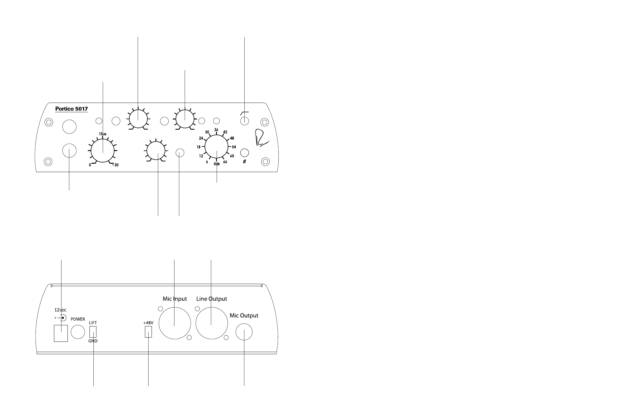
Portico 5017: Front Panel
DC Input
12V DC Input
Center Positive
Mic Input
TLA Fully Balanced Input
1=GND, 2=HOT 3=COLD
Line/Blend Output
Transformer Coupled
Fully Balanced and Floating
1=GND, 2=HOT 3=COLD
Ground Lift
Switch lifts the ground
connection for the instrument
input
48V
Provides Phantom Power on
the microphone input
Mic Output
Transformer Coupled
Fully Balanced and Floating
1=GND, 2=HOT 3=COLD
MAX
VARI
BLEND
SILK
COMP
THRESHOLD
INST
MIC
MIC GAIN
INST GAIN
MIN
-20
+10
INST
THRU
PHASE
PHASE SWEEP
INST
MIC
Mobile Pre/DI/Comp
COMP
Instrument Gain
Provides 0 to 30dB gain with a
continuously variable pot
Microphone Preamp
Provides 66dB of gain in 6dB
increments
Blend
Continuously variable mix
control between DI and Mic
Signals.
High Pass Filter
Reduces signals by
12dB/octave
Threshold
When signals exceed the
“threshold” level, the gain is
reduced at a 2:1 ratio, with a
constant attack and release
times.
Direct Input
1/4” input and thru for
instruments and line level
signals
Vari-phase
Continuously rotates the
phase of the instrument
signal
Silk
Adds nostalgic warmth and
presence to both outputs
when engaged
Portico 5017: Back Panel
MICROPHONE PREAMPLIFIER DESIGN NOTES
In former years, before the introduction of solid state amplifiers, transformers were necessary to
step up to the very high input impedance of tubes, and to provide a balanced input for the
microphone line. An input impedance of 1,000 or 1,200 ohms became established for microphones
having a source impedance of 150 or 200 ohms, with connection being made on a twisted twin
screened cable (This type of cable, while excellent for low impedance work, has high capacitance
between its conductors and between each conductor and screen. Resultant high frequency losses
are excessive with piezo pickups and may cause resonances with magnetic pickups.) Thus
microphones were not heavily loaded. Condenser microphones worked off high voltage supplies
(300V!) on the studio floor which polarized the diaphragms and powered a built-in pre-amplifier.
More and more microphones were needed as “Pop” music gained ground and this led to the popular
and efficient method of 48-volt “Phantom” powering that was built into the multi-channel recording
Console – in place of numerous bulky supplies littering the studio, a miniature pre-amplifier now
being fitted inside the microphone casing.
The 48-volt supply was fed to the microphone through balancing resistors so it was impossible for
this voltage to actually reach the microphone, resulting in low polarizing volts and virtual starvation of
the little pre-amp inside the microphone. Nevertheless amazingly good microphones were designed
and made, becoming the familiar product we use today. If a low value resistive load is connected to
the output of an amplifier, that amplifier has to produce power in order to maintain a voltage across
that load. Obviously if we want more voltage (output from the microphone) we need to provide a
larger supply for the amplifier or settle for a lighter load. A microphone is a voltage generator, not a
power amplifier. Most microphones give their most accurate performance when they are not loaded
by the input impedance of a traditional preamplifier. If the microphone uses an electronic circuit
(transformerless) output, a low value of load impedance can possibly stress the little microphone pre-
amplifier, causing slew rate and compression at high levels.
On the other hand, a high value of load impedance allows the microphone to “breathe” and give of
its best, this being particularly advantageous with very high level percussive sounds. If the microphone
has an inductive source (such as would be the case if it has a transformer output) a low value of load
impedance causes the high frequencies to roll off due to leakage inductance in the transformer in
addition to the above amplifier distortion (This can be an advantage with some microphones!).
For this reason we have provided a high value of input impedance that will load microphones to the
smallest possible extent and makes the best possible use of that limited “Phantom” 48-volts supply.
DYNAMIC RANGE
Traditionally, high quality microphones such as ribbons, had very low source impedances – as low as 30
ohms at the output of a ribbon matching transformer. Moving coil microphones were higher but had not
been standardized as they are today. Condenser microphones, before the days of semiconductors, used
tube head amplifiers that were coupled to the outgoing line with a transformer. Microphone amplifiers,
such as in a mixing console, also used tubes and these typically have a high input impedance.
Microphones are Voltage generators, not Power generators. It is always desirable to deliver the
maximum possible signal voltage into the amplifier. It was traditional to provide an amplifier input
impedance of about 1,000 or 1,200 ohms; about 5 or 6 times the source impedance of the microphone.
This provided relatively low loading on the microphone – whatever its type – and went a long way to
avoid voltage loss.