MK Plastics Axijet IO&M User Manual
Page 6
Stack
Place the stack and the gasketing provided in the position as shown in the submittal layout drawings. Never lift the
stacks by the wind band vanes as this could cause damage. Secure the stack onto the fan discharge flange with
the appropriate bolts and washers provided.
Inlet Plenum
Check the roof curb dimensions and position relative to the fan. Compare the values with those marked on MK Plastics
Certified drawings. The plenum shall be attached to the curb by means of ¼” lag screws or bolts. Heavier fasteners
may be required by code in your area.
Check the position of the backdraft (isolation) and bypass dampers. Refer to MK Plastics Certified drawings for damper
positions
Duct Installation
Efficient fan performance relies on the proper installation of inlet ducts (where factory inlet plenums are not provided).
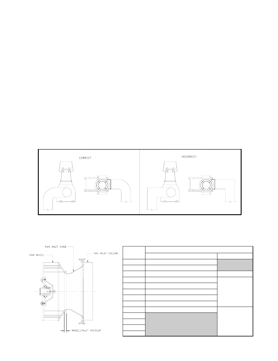
For duct inlets, allow at least 3 fan wheel diameters between duct turns or elbows and the fan inlet. See Fig. 9 below.
Fig. 9 – Inlet Duct Turns
Wheel-to-Inlet Overlap
The correct wheel-to-inlet overlap is critical to proper fan performance. This overlap should be verified before initial
start-up since rough handling during shipment could cause a shift in fan components. Refer to Fig. 10 - Wheel/Inlet
Overlap for details.
Page 6
Drains
Axijet fans and bypass air plenums are provided with integral drains. These drains are plugged at the factory prior to
shipment. Properly designed systems operating under normal conditions should experience no problems with en-
trained moisture or condensation. The Axijet system should not be operated with these connections open to the atmos-
phere.
Unique design practices, facility policy, or a specific application may require that these drains have the addition of a
manual valve or automatic drain trap.
In all situations, it is important to be aware of local piping codes and the fact that condensation from laboratory or pro-
cess exhausts can be hazardous and corrosive, paying special attention to the building roofing and drainage system.
Fan
Overlap
Size
FRP Axijets
Steel Axijets
1225
9/16”
1500
11/16”
1825
3/4"
5/8”
2450
1-1/32”
3000
1-5/16”
3650
1-1/2”
3/4”
4025
1-21/32”
4450
1-13/16”
4900
2”
5425
6000
1-1/4”
6600
7300
Fig. 10 – Wheel/Inlet Overlap