Installation overview wiring the wand, Important – Mighty Mule FM138 User Manual
Page 2
2 GTO Exit Wand Instructions 12.28.11
• The SENSOR is designed to detect iron-
based metal
in motion.
• The SENSOR’s ability to detect iron-based
metal objects is based on the mass, velocity
and proximity of the object to the sensor.
EXAMPLE - A child’s bicycle moving at 2
mph @ 1’ from the sensor has a similar
effect as a car moving at 2 mph @ 6’ from
the sensor.
• The SENSOR must be stationary to function
properly.
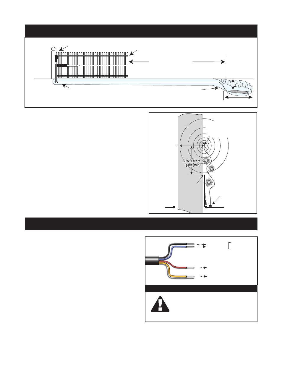
Gate Opener
Control Box
Driveway
RANGE:
12 ft. radius
(max)
SENSOR:
2 ft. from Driveway (max)
and12 in. deep
Open Gate
Outside Sensor
Range
( allow 5 ft. for wiring
to Control Box)
Gate Opener
Control Box
12”
Minimum of 25 feet
SENSOR: 2 feet from
driveway edge and
1 foot in ground
Open Gate
Outside Sensor
Range
PVC conduit in ground
and up to control box
recommended
24”
1.
Obtain the instruction manual for the
gate opener.
2.
Locate the control terminals (2) that
will
ONLY OPEN the gate.
3.
Verify that the above inputs when
shorted (a small wire connecting
the 2 terminals) will do all of the
following:
• OPEN the gate if the gate is idle.
• STOP and then OPEN the gate if gate is closing.
• DO NOTHING if the gate is opening.
Yellow
Black
Blue
RELAY OUTPUT
POWER INPUT =
Red
Braided
Ground
WAND
WIRING
11-30 Vdc
or
8-26 Vac
TO
OPEN ONLY
INPUT OF GATE
OPENER CONTROL
Normally open relay contacts,
closes for 2 seconds when
moving vehicle is detected.
+
–
IMPORTANT
DO NOT CONNECT THE POWER
INPUT WIRES TO THE POWER
SOURCE (i.e. 12 V battery) UNTIL
INSTRUCTED TO DO SO.
INSTALLATION OVERVIEW
WIRING THE WAND