Test keypad, Control board connections, Status program calling granted – Mighty Mule FM136 User Manual
Page 4
2
rev - 09-20-10
ON
ALARM
ACCESSORY
RCVR
SEQ1
SEQ2
LEARN
BLU
ORG
WHT
GRN
R B G
Connect
#1 wire from the
RELAY OUTPUT terminals
on the keypad to
WHT
terminal on the gate opener
control board.
Connect
#2 wire
from the
RELAY OUTPUT
terminals on the keypad to the
GRN terminal on the gate
opener control board.
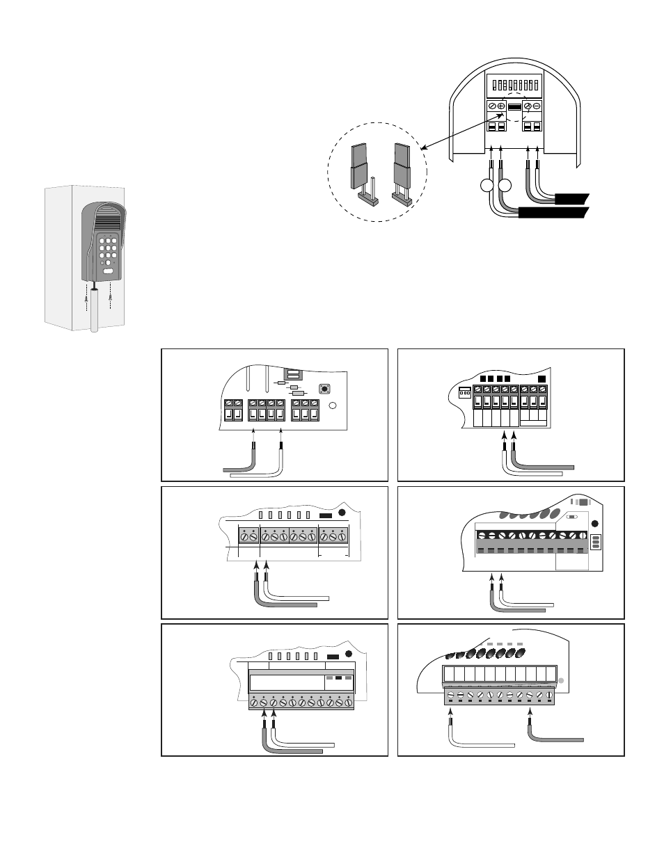
PRO-1000/2000, PRO-SL1000/SL2000 and Old Mighty Mule
Control Boards
#1
#2
RELAY
OUTPUT
AC/DC
POWER IN
1 2 3 4 5 6 7 8 9
+
0
–
Jumper ON
wireless mode
Jumper OFF
Hard-wire from Gate Opener
Power Supply from
Opener Battery
#
1
#
2
wired mode
Step 2:
Strip 3/16" off the ends of one pair of low voltage wires. Attach the wires to the terminal
block marked RELAY OUTPUT on the keypad control board as shown. Connect the other
end of the wires to the gate opener’s control board as shown in Control Board Connections
(below).
Step 3:
Strip 3/16" off the ends of the second pair of low voltage wires.
Attach the wires to the terminal block marked AC/DC POWER IN
on the keypad control board as shown. Connect the other end of
the wires to the opener’s battery: one end to the POSITIVE
(RED) pole and the other to the NEGATIVE (BLACK) pole.
Step 4:
Connect the jumper between the two terminals on the
keypad control board (ON) as shown.
Step 5:
Slide the keypad into the
housing and secure with the small
screws provided.
Step 6:
Replace the control board cover
and turn the power switch ON.
1
2
ABC
3
DEF
4
GHI
5
JKL
6
MNO
7
PRS
8
TUV
9
WXY
0
CALL
STATUS
PROGRAM
CALLING
GRANTED
Control Board Connections
If your control board doesn’t look like any of these diagrams, please refer to your gate opener
installation manual or call GTO Technical Service at 1-800-543-1236 or 850-575-4144.
GRN
B�K
R�D
RECEIVER
��M ��M
�����
�����
��
���
��
���
�AF�T�
�XIT
�P�N
�HAD�W
���P
��
���
�DG�
�P�N
�DG�
���
���
�8
��2
GTO/PRO DC Powered PRO-SW3000
and PRO-SW4000 Control Boards
Connect
#1 wire from the
RELAY OUTPUT terminals on
the keypad to
CYCLE terminal on
the gate opener control board.
Connect
#2 wire from
the
RELAY OUTPUT
terminals on the keypad
to the
COM terminal on
the gate opener control
board.
#1
#2
RECR
GRN
BLK
RED
EXIT
SAFETY
EDGE
CY
CLE
COMMON
LINK
Mighty Mule 350 Control Board
Connect
#1 wire from the
RELAY OUTPUT terminals
on the keypad to
CYCLE
terminal on the gate opener
control board.
Connect
#2 wire from the RELAY
OUTPUT terminals on the keypad
to the
COMMMON terminal on
the gate opener control board.
#1
#2
RECEIVER
COM COM
CY
CLE
CL
OSE
SAFETY
EXIT/ OPEN
SHADOW LOOP
CL
OSE
EDGE
OPEN EDGE
BLK
GRN
RED
Mighty Mule 500 & 502
Control Boards
Connect the
#1 wire from
RELAY OUTPUT terminals on the
keypad
to the
CYCLE terminal on
the opener control board.
Connect the
#2 wire from
the
RELAY OUTPUT
terminals on the keypad
to
one of the
COMMON
terminals on the opener
control board.
#1
#2
RECEIVER
ALM
GTO RCVR.
CO
M
GRN
BLK
RED
CY
CLE
SAFET
Y
EXIT
SHADO
W
OPEN EDGE
CO
M
CONTROL INPUTS
CL
OSE
EDGE
Connect
#1 wire from
the
RELAY OUTPUT terminals
on the keypad to
CYCLE terminal
on the gate opener control board.
Connect
#2 wire from the
RELAY OUTPUT terminals
on the keypad to the
COM
terminal on the gate opener
control board.
#1
#2
GEN-3 (Blue) Control Boards
COM
COM
COM
G
TO Inc.
SX4000 L
CY
CLE
SAFETY
OPEN EDGE
RUN 2
OPEN
CL
OSE
STOP
COM
COM
COM
SHADOW
LOOP
Connect
#1 wire from the
RELAY OUTPUT
terminals on the keypad to
CYCLE terminal on the
gate opener control board.
Connect
#2 wire from the
RELAY OUTPUT terminals
on the keypad to the
COM
terminal on the gate opener
control board.
#1
#2
GTO/PRO GP-SL100 and GP-SW100
Control Boards
3. Test Keypad
Turn the gate opener power switch to ON. Test the keypad by entering “1234.”