Lab.gruppen LAB 300 User Manual
Page 5
thermal limiting protection within less than 2
minutes. During this time, the temperature of the
power supply will be stabilised at a temperature
that will have no effect on the insulation rating of
the AC line cord.
Secondly, the maximum expected average
current under worst case program material which is
1/3 of full power according to the FTC-standard. At
this level the music will be in the state of constant
clip and is therefore the highest power level one
can obtain without completely obliterating the
program.
At last, the "normal operating power", as
measured according to the safety standard IEC 65
and used by a majority of safety agencies. The
normal operating power is measured using pink
noise, with an average output power equal to 1/8 of
full power. The one eighth of the total power is as
loud as you can play music while making some
attempt to avoid obvious clipping. It also
corresponds to a headroom of 9dB, which is very
low for an audio program.
In 2 ohms operation, the protection of the amplifier
circuit will not permit long term current draw and
the component temperature rise will stabilises well
below the rating.
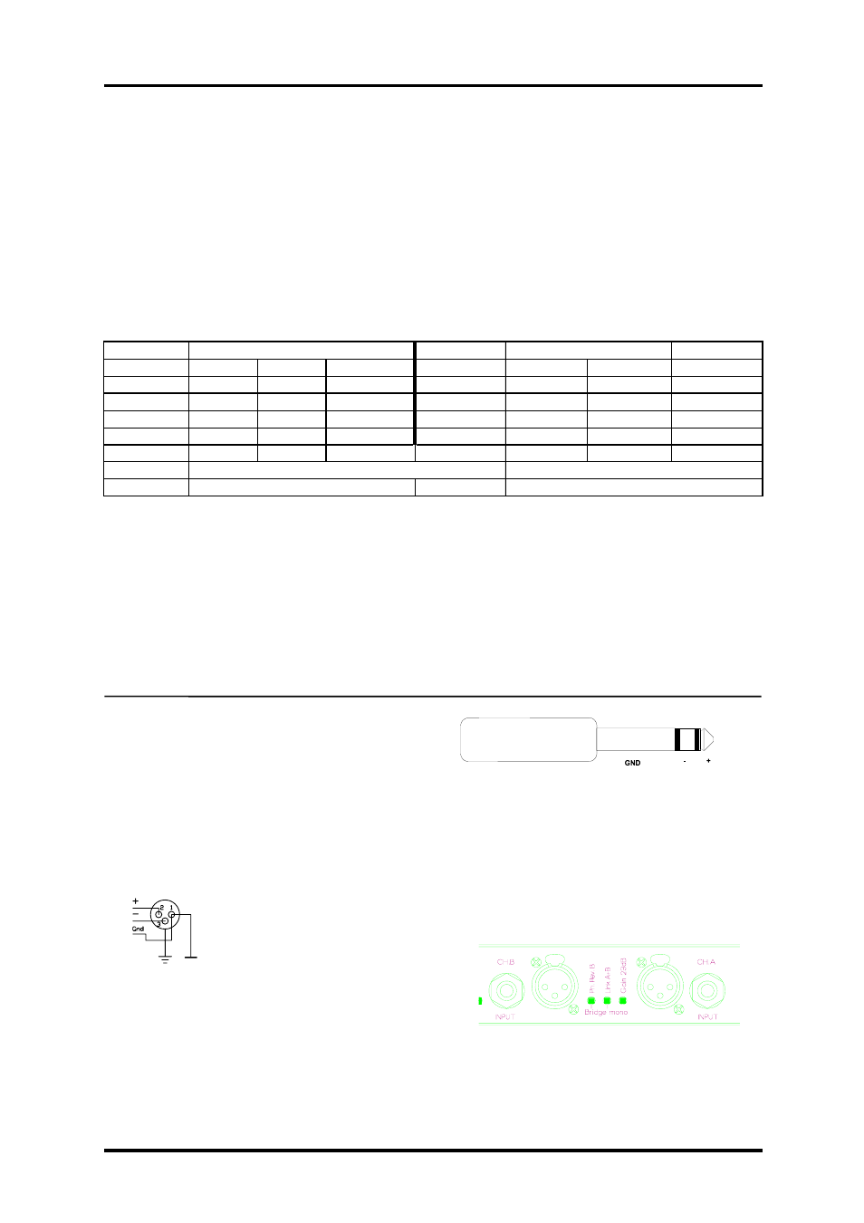
MAX OUTPUT POWER
MAINS INPUT POWER
Power
Full Power
1/3 Power
1/8 Power
Idle
sine wave
note 1
note 2
LAB 300
8 ohms
2X
100
400
100
100
70
4 ohms
2X
150
600
200
200
70
2 ohms
2X
160
800
300
200
70
note 1
Mean power with music as program source
Normal" music power with 9dB headroom,
The amplifier driven to clip level
note 2 IEC standard power rating.
Table 1.
The current draw can be calculated by dividing the mains input power by the mains voltage.
We recommend you to design the power distribution for at least the current at 1/8 power and 1/3 power for
heavy duty demands like discos etc.
The heat power can be calculated as the following example:
We consider a headroom of at least 9dB and a 4 ohms load on an amplifier producing 150 watts per channel.
The 1/8 power per channel is then; 150 / 8 = 19 watts, total output; 2 x 19 = 38 watts.
The power consumption according to the chart above is then 200 watts.
The heat power produced is the difference between the power consumption and output power;
200 - 38 = 162 watts per amplifier.
6. Input connections
XLR Input connectors are balanced and wired
according to the IEC 268, that is pin 2 hot, and wired
in the following way:
PIN 1
GROUND/SHIELD
PIN 2
HOT
PIN 3
COLD
Figure 3. XLR input connector pinout
There are also TRS jacks for linking etc. They are
wired as follows:
TIP HOT
RING COLD
SLEEVE SHIELD/GROUND
Figure 4. TRS phone plug
The input impedance is high enough (20 kohms
balanced) to allow ”daisy-chaining”, or multiple
parallel input connections. To daisy chain, use the
TRS jacks provided on each channel. The input
circuits also have a high enough headroom, to accept
the maximum output level from virtually any low
level signal source.
Figure 5. Rear panel connectors
Do not use XLR and TRS jacks on the same
channel simultaneously for mixing or other
purposes.
5