Operation – Lab.gruppen LAB 2002 User Manual
Page 8
8
To obtain an output, connect the speaker leads to pin
+1 on channel A Speakon to speaker positive
terminal and pin +1 on channel B Speakon to
speaker negative terminal . Do not connect either
of the -1 (negative) pins of the Speakons. Do not
connect speakers to channel A or B in the normal
manner in bridge mode, as this can cause serious
damage.
The recommended minimum nominal impedance
for bridged mono is 4 ohms (equivalent to driving
both channels at 2 ohms).
Driving bridged loads of less than 4 ohms may cause
a thermal overload.
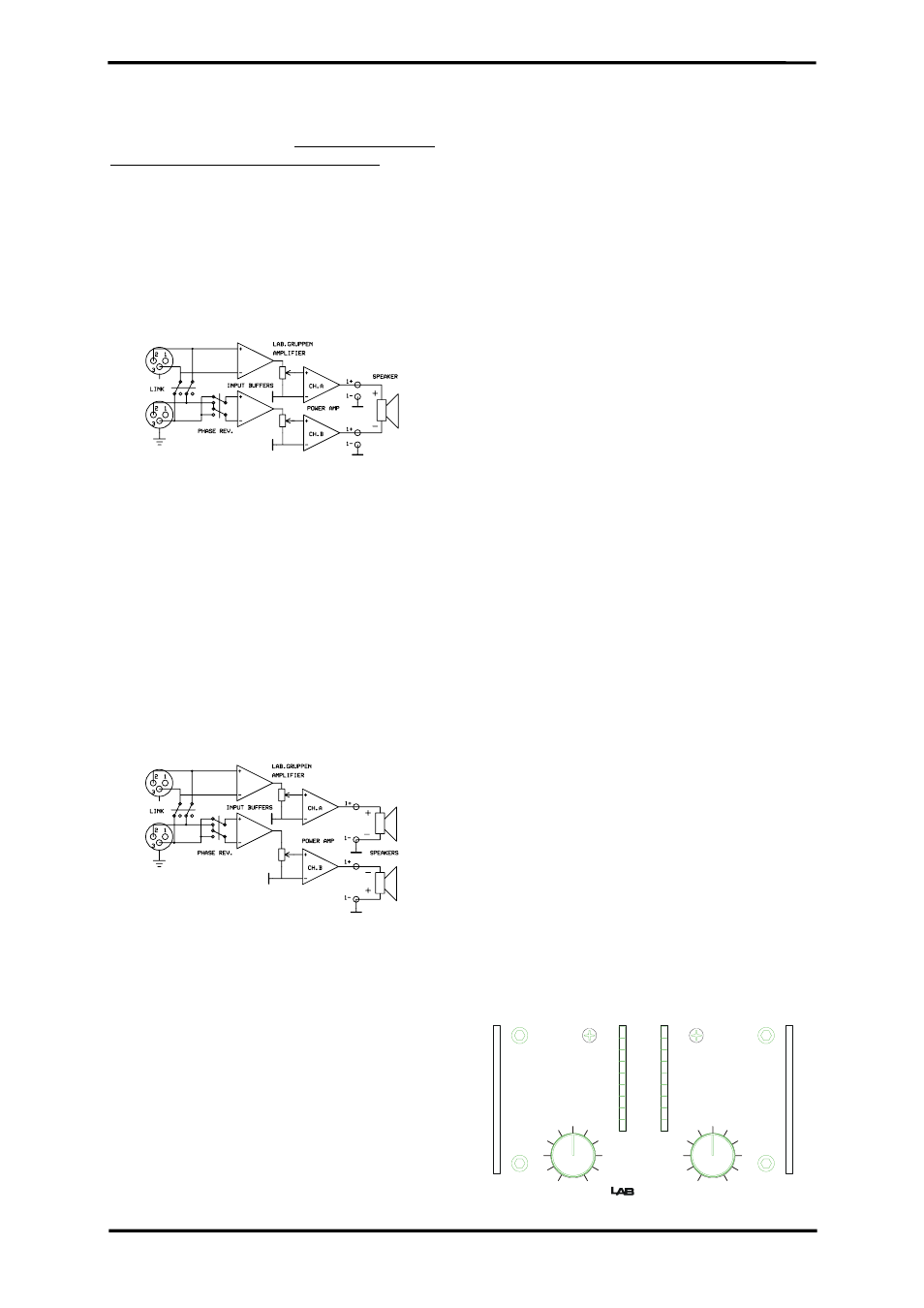
Figure 11. Bridge mono connection
Both level attenuators must be at the same position.
We recommend you to put them in the 0 dB (full)
position.
4. Stereo reverse
This mode is similar to the Tandem mono mode.
Apart from depressing the Link switch , you also
depress the Phase reverse switch, like in the Bridge
mono. Channel B is now phase reversed. To
compensate for that, connect pin +1 on channel B
Speakon to speaker negative terminal and pin -1
on channel B to speaker positive terminal.
Figure 12. Stereo reverse mode
Channel A output is connected as in the normal
stereo mode. By having channel A and B operating
in opposite polarity, the energy storage in the
power supply is more efficient. This means that the
amplifier can deliver up to 10% more power than in
tandem mono mode. This is significant for signals
below 100 Hz (sub bass etc.).
Operation
1. Operation
precautions
• Make sure that the power switch is off before
making any input or output connections or
operating the switches on rear panel. See pages
4-6 about installation.
• Make sure that the AC mains is correct and the
same as that is printed on the rear panel of the
amplifier. See pages 4-5 , about operating
voltage and power consumption.
• Make sure that the switches on the rear panel
for operation modes ,clip limiters, and the
MLS™ switches are in the correct position.
See pages 6-7, about operation modes, page 9
about clip limiters and page 7 for the MLS
switches.
• It is always a good idea to turn down the gain
controls during power up, to prevent speaker
• damage, if there is a high signal level at the
input.
2. Powering up -Soft start
When you power up the amplifier it takes a couple of
seconds to check its circuits (this is known as the
"soft start" or "slow start" sequence), the fans then
blow at high speed before going onto "idle" and the
two bottom green LED’s come on to show the output
circuits are receiving the correct rail voltage.
3. Input attenuators
The two input level attenuators on the front panel,
alter the signal level for their respective amplifier
channel in all modes. They are calibrated in dB to
help setting up active loudspeaker systems or cutting
down unwanted noise from the input signal.
In bridged mode, both controls must be in the same
position, so that the speaker load will be shared
equally between the channels.
4. Gain switch
The gain switch located on rear panel is for changing
the input sensitivity of the amplifier. This can be
handy when using low or high nominal input signals
e.g. most professional mixing consoles operate at a
nominal level of +4dBu therefore use the 29dB
position (depressed switch), to give you plenty of
fader movement. On the other hand, for a disco
mixer that operates at a nominal level of 0dBu, use
the upper position setting, which has a sensitivity of
0 dB for full power in 4 ohms.
2002
VHF
TEMP
CLIP
-5
-10
-15
-20
-25
ON
-80
-40
-20
-16
-12
-10
-7
-5
-3
-1
0
dB
CH. A
-80
-40
-20
-16
-12
-10
-7
-5
-3
-1
0
dB
CH. B